ST STM32F4-Discovery
The STM32F4Discover board (also known as STM32F407G-DISC1) is a low cost development board released by STMicroelectronics.
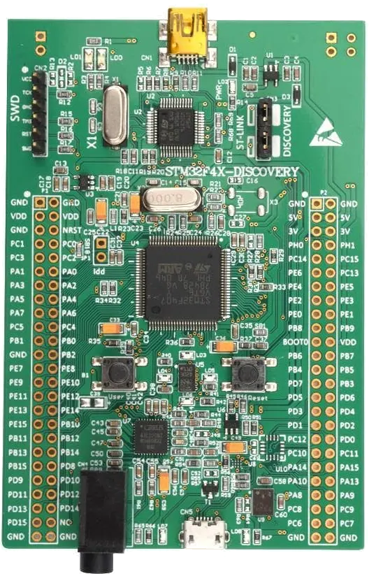
Features
- Processor
STM32F407VGT6 (Cortex-M4 running at 168MHz)
- Memory
192 KiB SRAM memory
1024 MiB Flash
- Connectivity
USB host/device (OTG) over Micro-AB connector
Note: the board also supports Ethernet, CAN, RS485 (but requires baseboard)
- Multimedia
Audio Input and Output (over P2 connector)
On-board ST-LINK/V2 for programming and debugging,
LIS302DL, ST MEMS motion sensor, 3-axis digital output accelerometer,
MP45DT02, ST MEMS audio sensor, omni-directional digital microphone,
CS43L22, audio DAC with integrated class D speaker driver,
Four user LEDs and two push-buttons,
Easy access to most MCU pins.
Refer to http://www.st.com/internet/evalboard/product/252419.jsp for further information about this board.
NOTE: This port was developed on the original board, order code STM32F4DISCOVERY. That board has been replaced with the new order code STM32F407VG-DISC1. The new version of the board differs in at least these ways:
The ST-LINK/V2 has been updated to ST-LINK/V2-A on STM32F407G-DISC1 with a Virtual Com port and Mass storage.
LIS3DSH ST MEMS 3-axis accelerometer
LEDs
The STM32F4Discovery board has four LEDs; green, orange, red and blue on the board. These LEDs are not used by the board port unless CONFIG_ARCH_LEDS is defined. In that case, the usage by the board port is defined in include/board.h and src/up_leds.c. The LEDs are used to encode OS-related events as follows:
SYMBOL
Meaning
LED1[1] green
LED2 orange
LED3 red
LED4 blue
LED_STARTED
NuttX has been started
ON
OFF
OFF
OFF
LED_HEAPALLOCATE
Heap has been allocated
OFF
ON
OFF
OFF
LED_IRQSENABLED
Interrupts enabled
ON
ON
OFF
OFF
LED_STACKCREATED
Idle stack created
OFF
OFF
ON
OFF
LED_INIRQ
In an interrupt[2]
ON
N/C
N/C
OFF
LED_SIGNAL
In a signal handler[3]
N/C
ON
N/C
OFF
LED_ASSERTION
An assertion failed
ON
ON
N/C
OFF
LED_PANIC
The system has crashed
N/C
N/C
N/C
ON
LED_IDLE
STM32 is is sleep mode
[1] If LED1, LED2, LED3 are statically on, then NuttX probably failed to boot and these LEDs will give you some indication of where the failure was
[2] The normal state is LED3 ON and LED1 faintly glowing. This faint glow is because of timer interrupts that result in the LED being illuminated on a small proportion of the time.
[3] LED2 may also flicker normally if signals are processed.
RGB LED Driver
Alan Carvalho de Assis has used the STM32F4-Discovery to drive an RGB LED using PWM output. The external RGB connected this way:
R = TIM1 CH1 on PE9
G = TIM2 CH2 on PA1
B = TIM3 CH3 on PB0
The RGB LED driver that uses PWM to control the red, green, and blue color components can be enabled with the following configuration settings:
+CONFIG_RGBLED=y

+CONFIG_PWM

+CONFIG_STM32_TIM1
+CONFIG_STM32_TIM2
+CONFIG_STM32_TIM3
+CONFIG_STM32_TIM1_PWM=y
+CONFIG_STM32_TIM1_MODE=0
+CONFIG_STM32_TIM1_CHANNEL=1
+CONFIG_STM32_TIM1_CHMODE=0
+CONFIG_STM32_TIM2_PWM=y
+CONFIG_STM32_TIM2_MODE=0
+CONFIG_STM32_TIM2_CHANNEL=2
+CONFIG_STM32_TIM2_CHMODE=0
+CONFIG_STM32_TIM3_PWM=y
+CONFIG_STM32_TIM3_MODE=0
+CONFIG_STM32_TIM3_CHANNEL=3
+CONFIG_STM32_TIM3_CHMODE=0
PWM
The STM32F4Discovery has no real on-board PWM devices, but the board can be configured to output a pulse train using TIM4 CH2 on PD3. This pin is available next to the audio jack.
UARTs
UART/USART PINS
USART1
Function
Pin
CK
PA8
CTS
PA11*
RTS
PA12*
RX
PA10*, PB7
TX
PA9*, PB6*
USART2
Function
Pin
CK
PA4*, PD7
CTS
PA0*, PD3
RTS
PA1, PD4*
RX
PA3, PD6
TX
PA2, PD5*
USART3
Function
Pin
CK
PB12, PC12*, PD10
CTS
PB13, PD11
RTS
PB14, PD12*
RX
PB11, PC11, PD9
TX
PB10*, PC10*, PD8
UART4
Function
Pin
RX
PA1, PC11
TX
PA0*, PC10*
UART5
Function
Pin
RX
PD2
TX
PC12*
USART6
Function
Pin
CK
PC8, PG7[2]
CTS
PG13[2], PG15[2]
RTS
PG12[2], PG8[]
RX
PC7[1], PG9[2]
TX
PC6, PG14[2]
[1] Indicates pins that have other on-board functions and should be used only with care (See table 5 in the STM32F4Discovery User Guide). The rest are free I/O pins.
[2] Port G pins are not supported by the MCU
Default USART/UART Configuration
USART2 is enabled in most configurations (see */defconfig). RX and TX are configured on pins PA3 and PA2, respectively (see include/board.h).
These pins selections, however, conflict with Ethernet pin usage on the STM32F4DIS-BB base board. The STM32F4DIS-BB base board provides RS-232 drivers and a DB9 connector for USART6. USART6 is the preferred serial console for use with the STM32F4DIS-BB.
Timer Inputs/Outputs
- ::
- TIM1
CH1 PA8, PE9 CH2 PA9[1], PE11 CH3 PA10[1], PE13 CH4 PA11[1], PE14
- TIM2
CH1 PA0[1], PA15, PA5[1] CH2 PA1, PB3[1] CH3 PA2, PB10[1] CH4 PA3, PB11
- TIM3
CH1 PA6[1], PB4, PC6 CH2 PA7[1], PB5, PC7[1] CH3 PB0, PC8 CH4 PB1, PC9
- TIM4
CH1 PB6[1], PD12[1] CH2 PB7, PD13[1] CH3 PB8, PD14[1] CH4 PB9[1], PD15[1]
- TIM5
CH1 PA0[1], PH10[2] CH2 PA1, PH11[2] CH3 PA2, PH12[2] CH4 PA3, PI0
- TIM8
CH1 PC6, PI5 CH2 PC7[1], PI6 CH3 PC8, PI7 CH4 PC9, PI2
- TIM9
CH1 PA2, PE5 CH2 PA3, PE6
- TIM10
CH1 PB8, PF6
- TIM11
CH1 PB9[1], PF7
- TIM12
CH1 PH6[2], PB14 CH2 PC15, PH9[2]
- TIM13
CH1 PA6[1], PF8
- TIM14
CH1 PA7[1], PF9
[1] Indicates pins that have other on-board functions and should be used only with care (See table 5 in the STM32F4Discovery User Guide). The rest are free I/O pins. [2] Port H pins are not supported by the MCU
Nintendo Wii Nunchuck
There is a driver on NuttX to support Nintendo Wii Nunchuck Joystick. If you want to use it please select these options:
Enable the I2C1 at System Type -> STM32 Peripheral Support, it will enable:
CONFIG_STM32_I2C1=y
Enable to Custom board/driver initialization at RTOS Features -> RTOS hooks:
CONFIG_BOARD_LATE_INITIALIZE=y
Enable the I2C Driver Support at Device Drivers, it will enable this symbol:
CONFIG_I2C=y
Nintendo Wii Nunchuck Joystick at Device Drivers -> [*] Input Device Support:
CONFIG_INPUT=y
CONFIG_INPUT_NUNCHUCK=y
Enable the Nunchuck joystick example at Application Configuration -> Examples:
CONFIG_EXAMPLES_NUNCHUCK=y
CONFIG_EXAMPLES_NUNCHUCK_DEVNAME="/dev/nunchuck0"
You need to connect GND and +3.3V pins from Nunchuck connector to GND and 3V of stm32f4discovery respectively (Nunchuck also can work connected to 5V, but I don’t recommend it). Connect I2C Clock from Nunchuck to SCK (PB6) and the I2C Data to SDA (PB9).
Quadrature Encoder:
The nsh configuration has been used to test the Quadrture Encoder (QEncoder, QE) with the following modifications to the configuration file:
These setting enable support for the common QEncode upper half driver:
CONFIG_BOARD_LATE_INITIALIZE=y

CONFIG_SENSORS=y
CONFIG_SENSORS_QENCODER=y
The timer 2 needs to be enabled:
CONFIG_STM32_TIM2=y
This is a board setting that selected timer 2 for use with the quadrature encode:
CONFIG_STM32F4DISCO_QETIMER=2
These settings enable the STM32 Quadrature encoder on timer 2:
CONFIG_STM32_TIM2_QE=y
CONFIG_STM32_QENCODER_FILTER=y
CONFIG_STM32_QENCODER_SAMPLE_EVENT_6=y
CONFIG_STM32_QENCODER_SAMPLE_FDTS_4=y
These settings enable the test case at apps/examples/qencoder:
CONFIG_EXAMPLES_QENCODER=y
CONFIG_EXAMPLES_QENCODER_DELAY=100
CONFIG_EXAMPLES_QENCODER_DEVPATH="/dev/qe0"
In this configuration, the QEncoder inputs will be on the TIM2 inputs of PA15 and PA1 (CH1 and CH2 respectively).
You can also use QEncoder with other timers, but keep in mind that only TIM2 and TIM5 are 32bits timers, all other timers are 16-bit then the QE counter will overflow after 65535.
If TIM4 is selected, then PB6 and PB7 will be used for CH1 and CH2. If TIM8 is selected, then PC6 and PI5 will be used for CH1 and CH2.
STM32F4DIS-BB
RTC DS1307
It is possible to use a low cost extern DS1307 RTC to keep date and time always updated. These DS1307 RTC modules come with a 3V button battery, then even when the board is turned OFF the Date/Time registers keep running.
You can connect the module this way (STM32F4Discovery to DS1307 board): GND to GND; 5V to VCC; PB9 to SDA; PB6 to SCL. In the NuttX menuconfig you need to enable these options:
System Type  --->
    STM32 Peripheral Support  --->
        [*] I2C1

Device Drivers  --->
    Timer Driver Support  --->
        [*] RTC Driver Support  --->
            -*-   Date/Time RTC Support
            [*]   External RTC Support
            [*]     DS130x/DS323x RTC Driver
                      Maxim Integrated RTC (DS1307)  --->
            (100000)  DS1307/DS323x I2C frequency

Application Configuration  --->
    NSH Library  --->
        Disable Individual commands  --->
            [ ] Disable date ( <-- Deselect )
It is also a good idea to enable the DEBUG to RTC initially, you will see:
ABCDF
stm32_ds1307_init: Initialize I2C1
stm32_ds1307_init: Bind the DS1307 RTC driver to I2C1
rtc_dumptime: Returning:
rtc_dumptime:    tm_sec: 00000039
rtc_dumptime:    tm_min: 00000001
rtc_dumptime:   tm_hour: 00000009
rtc_dumptime:   tm_mday: 00000016
rtc_dumptime:    tm_mon: 00000008
rtc_dumptime:   tm_year: 00000077

NuttShell (NSH)
nsh> date
Sep 22 09:01:58 2019
SSD1289
I purchased an LCD display on eBay from China. The LCD is 320x240 RGB565 and is based on an SSD1289 LCD controller and an XPT2046 touch IC. The pin out from the 2x16 connect on the LCD is labelled as follows:
LCD CONNECTOR:          SSD1289 MPU INTERFACE PINS:

   +------+------+      DEN     I  Display enable pin
1  | GND  | 3V3  |  2   VSYNC   I  Frame synchronization signal
   +------+------+      HSYNC   I  Line synchronization signal
3  | D1   | D0   |  4   DOTCLK  I  Dot clock and OSC source
   +------+------+      DC      I  Data or command
5  | D3   | D2   |  6   E (~RD) I  Enable/Read strobe
   +------+------+      R (~WR) I  Read/Write strobe
7  | D5   | D4   |  8   D0-D17  IO For parallel mode, 8/9/16/18 bit interface
   +------+------+      WSYNC   O  RAM write synchronizatin output
9  | D7   | D6   | 10   ~RES    I  System reset
   +------+------+      ~CS     I  Chip select of serial interface
11 | D9   | D8   | 12   SCK     I  Clock of serial interface
   +------+------+      SDI     I  Data input in serial mode
13 | D11  | D10  | 14   SDO     O  Data output in serial moce
   +------+------+
15 | D13  | D12  | 16
   +------+------+
17 | D15  | D14  | 18
   +------+------+
19 | RS   | CS   | 20
   +------+------+
21 | RD   | WR   | 22  NOTES:
   +------+------+
23 |BL_CNT|RESET | 24  BL_CNT is the PWM backlight level control.
   +------+------+
25 |TP_RQ |TP_S0 | 26  These pins are for the touch panel: TP_REQ
   +------+------+     TP_S0, TP_SI, TP_SCX, and TP_CS
27 | NC   |TP_SI | 28
   +------+------+
29 | NC   |TP_SCX| 30
   +------+------+
31 | NC   |TP_CS | 32
   +------+------+
MAPPING TO STM32 F4:
  ---------------- -------------- ----------------------------------
   STM32 FUNCTION  LCD PIN       STM32F4Discovery PIN
  ---------------- -------------- ----------------------------------
   FSMC_D0          D0     pin 4   PD14 P1 pin 46 Conflict (Note 1)
   FSMC_D1          D1     pin 3   PD15 P1 pin 47 Conflict (Note 2)
   FSMC_D2          D2     pin 6   PD0  P2 pin 36 Free I/O
   FSMC_D3          D3     pin 5   PD1  P2 pin 33 Free I/O
   FSMC_D4          D4     pin 8   PE7  P1 pin 25 Free I/O
   FSMC_D5          D5     pin 7   PE8  P1 pin 26 Free I/O
   FSMC_D6          D6     pin 10  PE9  P1 pin 27 Free I/O
   FSMC_D7          D7     pin 9   PE10 P1 pin 28 Free I/O
   FSMC_D8          D8     pin 12  PE11 P1 pin 29 Free I/O
   FSMC_D9          D9     pin 11  PE12 P1 pin 30 Free I/O
   FSMC_D10         D10    pin 14  PE13 P1 pin 31 Free I/O
   FSMC_D11         D11    pin 13  PE14 P1 pin 32 Free I/O
   FSMC_D12         D12    pin 16  PE15 P1 pin 33 Free I/O
   FSMC_D13         D13    pin 15  PD8  P1 pin 40 Free I/O
   FSMC_D14         D14    pin 18  PD9  P1 pin 41 Free I/O
   FSMC_D15         D15    pin 17  PD10 P1 pin 42 Free I/O
   FSMC_A16         RS     pin 19  PD11 P1 pin 27 Free I/O
   FSMC_NE1         ~CS    pin 10  PD7  P2 pin 27 Free I/O
   FSMC_NWE         ~WR    pin 22  PD5  P2 pin 29 Conflict (Note 3)
   FSMC_NOE         ~RD    pin 21  PD4  P2 pin 32 Conflict (Note 4)
   PC6              RESET  pin 24  PC6  P2 pin 47 Free I/O
   Timer output     BL_CNT pin 23  (to be determined)
  ---------------- -------------- ----------------------------------

1 Used for the RED LED
2 Used for the BLUE LED
3 Used for the RED LED and for OTG FS Overcurrent.  It may be okay to use
  for the parallel interface if PC0 is held high (or floating).  PC0 enables
  the STMPS2141STR IC power switch that drives the OTG FS host VBUS.
4 Also the reset pin for the CS43L22 audio Codec.
NOTE: The configuration to test this LCD configuration is available at boards/arm/stm32f4/stm32f4discovery/nxlines. As of this writing, I have not seen the LCD working so I probably have some things wrong.
I might need to use a bit-banging interface. Below is the pin configuration of a similar LCD to support a (write-only), bit banging interface:
LCD PIN   BOARD CONNECTION
LEDA      5V
VCC       5V
RD        3.3V
GND       GND
DB0-7     Port C pins configured as outputs
DB8-15    Port A pins configured as outputs
RS        Pin configured as output
WR        Pin configured as output
CS        Pin configured as output
RSET      Pin configured as output
The following summarize the bit banging operations:
/* Rese the LCD */
void Reset(void)
{
  Set RSET output
  delay
  Clear RSET output
  delay
  Set RSET output
}

/* Write 16-bits of whatever */
void Write16(uint8_t ms, uint8_t ls)
{
  Set port A to ms
  Set port B to ls

  Clear WR pin
  Set   WR pin
}

/* Set the index register to an LCD register address */
void Index(uint8_t address)
{
  Clear RS
  Write16(0, address);
}

/* Write data to the LCD register or GRAM memory */
void WriteData(uin16_t data)
{
  Set RS
  Write16(data >> 8, data & 0xff);
}

/* Write to a register */
void WriteRegister(uint8_t address, uint16_t data)
{
  Index(address);
  WriteData(data);
}
UG-2864AMBAG01 / UG-2864HSWEG01
I purchased an OLED display on eBay. The OLED is 128x64 monochrome and is based on an UG-2864AMBAG01 OLED controller. The OLED can run in either parallel or SPI mode. I am using SPI mode. In SPI mode, the OLED is write only so the driver keeps a 128*64/8 = 1KB framebuffer to remember the display contents:
Here is how I have the OLED connected. But you can change this with the settings in include/board.h and src/stm324fdiscovery.h. Connector pinout for the UG-2864AMBAG01 is specific to the theO.net display board that I am using:
--------------------------+----------------------------------------------
Connector CON10 J1:       | STM32F4Discovery
--------------+-----------+----------------------------------------------
CON10 J1:     | CON20 J2: | P1/P2:
--------------+-----------+----------------------------------------------
1  3v3        | 3,4 3v3   | P2 3V
3  /RESET     | 8 /RESET  | P2 PB6 (Arbitrary selection)
5  /CS        | 7 /CS     | P2 PB7 (Arbitrary selection)
7  A0         | 9 A0      | P2 PB8 (Arbitrary selection)
9  LED+ (N/C) | -----     | -----
2  5V Vcc     | 1,2 Vcc   | P2 5V
4  DI         | 18 D1/SI  | P1 PA7 (GPIO_SPI1_MOSI == GPIO_SPI1_MOSI_1 (1))
6  SCLK       | 19 D0/SCL | P1 PA5 (GPIO_SPI1_SCK == GPIO_SPI1_SCK_1 (1))
8  LED- (N/C) | -----     | ------
10 GND        | 20 GND    | P2 GND
--------------+-----------+----------------------------------------------
(1) Required because of on-board MEMS
-------------------------------------------------------------------------
Darcy Gong recently added support for the UG-2864HSWEG01 OLED which is also an option with this configuration. I have little technical information about the UG-2864HSWEG01 interface (see boards/arm/stm32f4/stm32f4discovery/src/up_ug2864hsweg01.c).
NiceRF LoRa (2AD66-LoRa V2)
It is possible to wire an external LoRa module to STM32F4Discovery board.
First connect the GND and VCC (to 3.3V) and then connect the SCK label to PA5, connect the MISO to PA6, connect the MOSI to PA7, connect the NSS to PD8, connect DIO0 to PD0 and finally connect NRESET to PD4.
Ethernet SPI Module ENC28J60
You can use an external Ethernet SPI Module ENC28J60 with STM32F4Discovery board.
First connect the GND and VCC (to 3.3V). Note: according with ENC28J60 datasheet the Operating Voltage should be between 3.1V to 3.6V, but STM32F4Discover only supply 3.0V. You can modify your board to supply 3.3V: just remove the D3 diode and short-circuit the board pads where it was soldered).
Connect the SCK label to PA5, connect the SO to PA6, connect the SI to PA7, connect the CS to PA4, connect RST to PE1 and finally connect INT to PE4.
The next step is to enable the ENC28J60 in the menuconfig (“make menuconfig”) and the necessary Network configuration, you can use the boards/arm/stm32f1/fire-stm32v2/configs/nsh/defconfig as reference.
HCI UART
BT860
I have been testing with the DVK_BT960_SA board via J10 as follows:
DVK_BT860-SA J10     STM32F4 Discovery P1
pin 1  GND                             P1 pin 49
pin 2  Module_RTS_O  USART3_CTS PB13,  P1 pin 37
pin 3  N/C
pin 4  Module_RX_I   USART3_TXD PB10,  P1 pin 34
pin 5  Module_TX_O   USART3_RX  PB11,  P1 pin 35
pin 6  Module_CTS_I  USART3_RTS PB14,  P1 pin 38
Due to conflicts, USART3 many not be used if Ethernet is enabled with the STM32F4DIS-BB base board:
PB-11 conflicts with Ethernet TXEN
PB-13 conflicts with Ethernet TXD1
If you need to use the HCI uart with Ethernet, then you will need to configure a new U[S]ART and/or modify the pin selections in include/board.h.
CC2564
[To be provided]
One confusing thing compared with the BT860 is in the naming of the pins at the 4-pin RS232 TTL interface: The BT860 uses BT860-centric naming, the Rx pin is for BT860 receive and needs to connect with the STM32 Tx pin, the Tx pin is for BT860 transmit an needs to be connected with the STM32 Rx pin, etc. The CC2564, on the hand, uses host-centric naming so that the CC2564 Rx pin connects to the STM32 Rx pin, Tx to Tx pin, etc.
Troubleshooting
First you should enable CONFIG_DEBUG_WIRELESS_ERR, WARN, and INFO options so that you can see what the driver is doing.
The bring-up problems that I encountered mostly involved setting up the 4-wire UART interface: Remember to cross Rx/Tx and RTS/CTS. The active state for RTS and CTS is low. For bringup of the BT860, I used a Seleae logic analyzer connected to the Tx, Rx, RTS, and CTS pins. When the BT860 is working correctly you would see this:
All signals high initially,
When NuttX starts, RTS goes low
The BT860 sees RTS go low and responds by setting CTS low after a delay. This is when it selects between USB and UART.
After another delay, the STM32 sends the 4 Tx bytes.
The BT860 responds with 3 bytes.
If successful, additional commands and responses follow.
Some of these steps may be different for other HCI UARTs. Steps 4-5 are the reset sequence. the 4 Tx bytes comes from the code in the function hci_initialize() in the file wireless/bluetooth/bt_hcicore.c:
/* Send HCI_RESET */

bt_hci_cmd_send(BT_HCI_OP_RESET, NULL);
The code is actually working one command ahead. It has already queued up the reset command and is requesting the HCI UART device features while the reset command is being sent:
ret = bt_hci_cmd_send_sync(BT_HCI_OP_READ_LOCAL_FEATURES, NULL, &rsp);
if (ret < 0)
  {
    wlerr("ERROR:  bt_hci_cmd_send_sync failed: %d\n", ret);
    return ret;
  }
A common failure is to see a timeout error (-116) due to a Tx flow control failure (CTS is high). There is no timeout on the first command, the timeout actually occurs on the second command in bt_hci_cmd_send_sync():
do
  {
    /* The timed wait could also be awakened by a signal */

    ret = nxsem_timedwait(&sync_sem, &abstime);
  }
while (ret == -EINTR);
The above times out and generates the 116 error.
In the case of the timeout, the second command is stuck in the message queue is never processed because the Tx thread is waiting for the BT_HCI_OP_RESET command to complete. It is blocked in hci_tx_thread() kernel thread.
The Tx occurs on a kernel thread. The Tx send of the first command causes the hci_tx_kthread() to block. It waits here until what the HCI UART receives the command and responses with the command complete event:
/* Wait until ncmd > 0 */

  do
    {
      ret = nxsem_wait(&g_btdev.ncmd_sem);
    }
  while (ret == -EINTR);
bt_hci_cmd_send() will block on the first BT_HCI_OP_RESET until until it gets the 3-byte event (BT_EVT) that indicates that the command was completed and provides the command status. See the function hci_command_complete() where it posts g_btdev.ncmd_sem.:
g_btdev.ncmd = 1;
nxsem_post(&g_btdev.ncmd_sem);
You can see such a hange in the wireless debug output:
bt_hci_cmd_send: opcode 0c03 len 3                          <<< BT_HCI_OP_RESET command is queue
hci_tx_kthread: Sending command 0c03 buf 20002a40 to driver <<< Sent to driver from the Tx thread
hciuart_write: config 801d924 buffer 20002760 buflen 4      <<< Goes to STM32 HCI UART driver

bt_hci_cmd_send_sync: opcode 1003 len 3                     <<< next command is queued.
hciuart_copytotxfifo: txhead 1 txtail 4 nbytes 1            <<< One byte of first command written to Tx HR
hciuart_enableints: CR1 000020ac CR2 00000301               <<< Tx interrupts enabled
!!!! No Tx interrupts, probably because of Tx flow control (CTS is high) !!!:
hci_initialize: ERROR: bt_hci_cmd_send_sync failed: -116 <<< Times out on second message
BASIC
I have used the stm32f4discovery/nsh configuration to test Michael Haardt’s BASIC interpreter that you can find at apps/interpreters/bas.:
Bas is an interpreter for the classic dialect of the programming language
BASIC.  It is pretty compatible to typical BASIC interpreters of the 1980s,
unlike some other UNIX BASIC interpreters, that implement a different
syntax, breaking compatibility to existing programs.  Bas offers many ANSI
BASIC statements for structured programming, such as procedures, local
variables and various loop types.  Further there are matrix operations,
automatic LIST indentation and many statements and functions found in
specific classic dialects.  Line numbers are not required.
There is also a test suite for the interpreter that can be found at apps/examples/bastest.
BAS
Below are the recommended configuration changes to use BAS with the stm32f4discovery/nsh configuration:
Dependencies:
CONFIG_LIBC_EXECFUNCS=y      : exec*() functions are required
CONFIG_LIBM=y                : Some floating point library is required
CONFIG_LIBC_FLOATINGPOINT=y  : Floating point printing support is required
CONFIG_LIBC_TMPDIR="/tmp"    : Writable temporary files needed for some commands
CONFIG_FS_FAT=y              : With FAT you create a RAMDISK at /tmp
CONFIG_FAT_LFN=y             : FAT is difficult to use with long file names
Enable the BASIC interpreter. Other default options should be okay:
CONFIG_INTERPRETERS_BAS=y    : Enables the interpreter
CONFIG_INTERPRETERS_BAS_VT100=y
The BASIC test suite can be included:
CONFIG_FS_ROMFS=y           : ROMFS support is needed
CONFIG_EXAMPLES_BASTEST=y   : Enables the BASIC test setup
CONFIG_EXAMPLES_BASTEST_DEVMINOR=0
CONFIG_EXAMPLES_BASTEST_DEVPATH="/dev/ram0"
Usage
This setup will initialize the BASIC test (optional): This will mount a ROMFS file system at /mnt/romfs that contains the BASIC test files:
nsh> bastest
Registering romdisk at /dev/ram0
Mounting ROMFS filesystem at target=/mnt/romfs with source=/dev/ram0
nsh>
These steps will create and mount a RAMDISK at /tmp (required only for a few BASIC commands). This will create a RAMDISK device at /dev/ram1 with size = 512 * 64 = 32KiB and mount it at /tmp:
nsh> mkrd -m 1 -s 512 64
nsh> mkfatfs /dev/ram1
nsh> mount -t vfat /dev/ram1 /tmp
nsh>
The interactive interpreter is started like:
nsh> bas
bas 2.4
Copyright 1999-2014 Michael Haardt.
This is free software with ABSOLUTELY NO WARRANTY.
>

Ctrl-D exits the interpreter.
The test programs can be ran like this:
nsh> bastest
Registering romdisk at /dev/ram0
Mounting ROMFS filesystem at target=/mnt/romfs with source=/dev/ram0
nsh> bas /mnt/romfs/test01.bas
 1
hello
 0.0002
 0.0000020
 0.0000002

nsh>
Or you can load a test into memory and execute it interactively:
nsh> bas
bas 2.4
Copyright 1999-2014 Michael Haardt.
This is free software with ABSOLUTELY NO WARRANTY.
> load "/mnt/romfs/test01.bas"
> run
 1
hello
 0.0002
 0.0000020
 0.0000002
>
Testing LLVM LIBC++ with NuttX
You can use LLVM LIBC++ on NuttX to get a C++ compiler with C++11 features. Follow these steps to get it working:
Clone the needed repositories:
$ git clone https://www.bitbucket.org/acassis/libcxx

$ git clone https://www.bitbucket.org/nuttx/apps

$ git clone https://www.bitbucket.org/nuttx/nuttx
Install the libcxx files on NuttX:
$ cd libcxx

$ ./install.sh ../nuttx
Installing LLVM/libcxx in the NuttX source tree
Installation succeeded
Enter inside NuttX and compile it:
$ cd ../nuttx

$ tools/configure.sh stm32f4discovery:testlibcxx
  Copy files
  Refreshing...

$ ls -l nuttx.bin
-rwxrwxr-x 1 alan alan 58112 Ago  8 11:08 nuttx.bin
Plug the MiniUSB cable in the STM32F4Discovery board and flash the firmware:
$ sudo openocd -f interface/stlink-v2.cfg -f target/stm32f4x.cfg -c init \
-c "reset halt" -c "flash write_image erase nuttx.bin 0x08000000"

...

Info : device id = 0x10036413
Info : flash size = 1024kbytes
target halted due to breakpoint, current mode: Thread
xPSR: 0x61000000 pc: 0x20000046 msp: 0x20001d60
wrote 65536 bytes from file nuttx.bin in 2.959432s (21.626 KiB/s)
Connect the USB/Serial 3.3V dongle to PA2(board TX) and PA3(board RX) use minicom or other serial console configured to 115200 8n1.
Press Reset pin of the board and you will see:
NuttShell (NSH)
nsh> ?
help usage:  help [-v] [<cmd>]

  [           cmp         free        mh          source      usleep
  ?           dirname     help        mv          sleep       xd
  basename    dd          hexdump     mw          test
  break       echo        kill        pwd         time
  cat         exec        ls          rm          true
  cd          exit        mb          rmdir       uname
  cp          false       mkdir       set         unset

Builtin Apps:
  helloxx

nsh>
Just type helloxx:
nsh> helloxx
helloxx_main: Saying hello from the dynamically constructed instance
CHelloWorld::HelloWorld: Hello, World!!
helloxx_main: Saying hello from the instance constructed on the stack
CHelloWorld::HelloWorld: Hello, World!!
helloxx_main: Saying hello from the statically constructed instance
CHelloWorld::HelloWorld: Hello, World!!

nsh>
Configurations
Common Information
Each STM32F4Discovery configuration is maintained in a sub-directory and can be selected as follow:
tools/configure.sh STM32F4Discovery:<subdir>
Where <subdir> is one of the sub-directories listed in the next paragraph
NOTES (common for all configurations):
This configuration uses the mconf-based configuration tool. To change this configuration using that tool, you should:
Build and install the kconfig-mconf tool. See nuttx/README.txt see additional README.txt files in the NuttX tools repository.
Execute ‘make menuconfig’ in nuttx/ in order to start the reconfiguration process.
Configuration Sub-directories
audio
This configuration is a variant of the NSH configuration used for demonstrating PCM audio using the CS43L22 stereo DAC/amplifier on board the STM32F4 Discovery and the STM32 I2S DMA interface. It uses the file player at apps/system/nxplayer. The serial console is on USART2.
The original CS43L22 and STM32 I2S drivers were contributed by Taras Drozdovsky in May of 2017. The audio configuration was contributed by Alan Carvalho de Assis and derives, in part, from the work of Taras at https://github.com/tdrozdovskiy/CS43L22-Audio-driver.
Usage instructions from the README file at the location:
Prepare USB flash storage. This configuration depends on .WAV files provided to the system via a USB flash stick. There are some sample audio files at https://github.com/tdrozdovskiy/CS43L22-Audio-driver and these steps will put those sample .WAV files onto the USB flash:
Format the USB flash storage into FAT. For example by next command:
$ mkfs.vfat /dev/sdb1
Create folder /music:
$ mkdir music
Copy files from /audio_samples/ to /music folder of USB flash storage:
$ cp <repo>/audio_samples/* /mnt/media/music/
You should be able to use either Taras’ .wav files like that or, if you like, your own compatible .wav files.
Example usage CS43L22 Audio driver
Power On or reset the STM32F4 Discovery board. We can see the NuttX command line prompt:
NuttShell (NSH)
nsh>
Mount the usb flash device into our file system:
nsh> mount -t vfat /dev/sda/ /mnt/sda
Start the NxPlayer program and Enter the help command to view the list of commands:
nsh> nxplayer
NxPlayer version 1.04
h for commands, q to exit
nxplayer> h
NxPlayer commands
================
balance d%      : Set balance percentage (< 50% means more left)
device devfile  : Specify a preferred audio device
h               : Display help for commands
help            : Display help for commands
mediadir path   : Change the media directory
play filename   : Play a media file
pause           : Pause playback
resume          : Resume playback
stop            : Stop playback
tone freq secs  : Produce a pure tone
q               : Exit NxPlayer
quit            : Exit NxPlayer
volume d%       : Set volume to level specified
Play the test sample track (cu44k.wav - 44100Hz, 16bit, stereo).:
nxplayer> play cu44k.wav
Set the volume value to 50%.:
nxplayer> volume 50
Stop the current track and play another one:
nxplayer> stop
nxplayer> play hn.wav
cxxtest
The C++ standard library test at apps/testing/cxxtest configuration. This test is used to verify the uClibc++ port to NuttX. This configuration may be selected as follows:
tools/configure.sh sim:cxxtest
NOTES:
- Before you can use this example, you must first install the uClibc++
C++ library. This is located outside of the NuttX source tree in the NuttX uClibc++ GIT repository. See the README.txt file there for instructions on how to install uClibc++
Ideally, you should build with a toolchain based on GLIBC or uClibc++. It you use a toolchain based on newlib, you may see an error like the following:
.../lib/libsupc++.a(vterminate.o): In function `__gnu_cxx::__verbose_terminate_handler()':
vterminate.cc:(....): undefined reference to `_impure_ptr'
Here is a quick’n’dirty fix:
Get the directory where you can find libsupc++::
arm-none-eabi-gcc -mcpu=cortex-m4 -mthumb -print-file-name=libsupc++.a
Go to that directory and save a copy of vterminate.o (in case you want to restore it later:
cd <the-directory-containing-libsupc++.a>
arm-none-eabi-ar.exe -x libsupc++.a vterminate.o
Then remove vterminate.o from the library. At build time, the uClibc++ package will provide a usable replacement vterminate.o.
Steps 2 and 3 will require root privileges on most systems (not Cygwin).
Now NuttX should link with no problem. If you want to restore the vterminate.o that you removed from libsupc++, you can do that with:
arm-none-eabi-ar.exe rcs libsupc++.a vterminate.o
Exceptions are enabled and workking (CONFIG_CXX_EXCEPTION=y)
elf
This configuration uses apps/examples/elf in order to test the ELF loader.
NOTES:
Default platform/toolchain:
CONFIG_HOST_WINDOWS=y                   : Windows
CONFIG_WINDOWS_CYGWIN=y                 : Cygwin environment on Windows
CONFIG_ARM_TOOLCHAIN_GNU_EABI=y      : GNU EABI toolchain for Windows
By default, this project assumes that you are NOT using the DFU bootloader.
It appears that you cannot execute from CCM RAM. This is why the following definition appears in the defconfig file:
CONFIG_STM32_CCMEXCLUDE=y
This configuration requires that you have the genromfs tool installed on your system and that you have the full path to the installed genromfs executable in PATH variable (see apps/examples/README.txt)
This configuration can be extended to use the hello++4 example and to build uClibc with the following additions to the configuration file (from Leo aloe3132):
CONFIG_HAVE_CXXINITIALIZE=y

CONFIG_UCLIBCXX=y
CONFIG_CXX_EXCEPTION=y
CONFIG_LIBSUPCXX=y
CONFIG_UCLIBCXX_BUFSIZE=32

CONFIG_EXAMPLES_ELF_CXX=y
By default, this configuration uses the ROMFS file system. It can also be modified to use the compressed CROMFS:
-CONFIG_PATH_INITIAL="/mnt/romfs"
+CONFIG_PATH_INITIAL="/mnt/cromfs"

-CONFIG_FS_ROMFS=y
+CONFIG_FS_CROMFS=y

-CONFIG_EXAMPLES_ELF_ROMFS=y
+CONFIG_EXAMPLES_ELF_CROMFS=y
The network initialization thread is enabled in this configuration. As a result, networking initialization is performed asynchronously with NSH bring-up.
The network monitor is not enabled in this configuration, however, so the firmware will not know when the network is disconnected or reconnected. The NSH Network Monitor cannot be used with the STM32F4DIS-BB base board because the LAN8720 is configured in REF_CLK OUT mode. In that mode, the PHY interrupt is not supported. The NINT pin serves as REFLCK0 in that case.
hciuart
This configuration was used for test the HCI UART driver. The HCI UART is enabled on USART3 as well as the test application at apps/wireless/bluetooth/btsak.
NOTES:
This configuration assumes that that you are using the STM32F4DIS-BB base board with serial console on USART6. If you are not using the STM32F4DIS-BB, then you will want to disable support for the base board.:
-CONFIG_STM32F4DISBB=y
+# CONFIG_STM32F4DISBB is not set
You may also want to reconfigure the serial console to USART1.
The HCI UART is assumed to connect to the UART3 on the following pins:
USART3 TX :  PB10
USART3 RX :  PB11
USART3 CTS:  PB13
USART3 RTS:  PB14
The HCI UART selection can be changed by re-configuring and assigning the different U[S]ART to the HCI. The U[S]ART pin selections can be changed by modifying the disambiguation definitions in boards/arm/stm32f4/stm32f4discovery/include/board.h
I have been testing with the DVK_BT960_SA board via J10 as follows:
DVK_BT860-SA J10     STM32F4 Discovery P1
pin 1  GND                             P1 pin 49
pin 2  Module_RTS_O  USART3_CTS PB13,  P1 pin 37
pin 3  N/C
pin 4  Module_RX_I   USART3_TXD PB10,  P1 pin 34
pin 5  Module_TX_O   USART3_RX  PB11,  P1 pin 35
pin 6  Module_CTS_I  USART3_RTS PB14,  P1 pin 38
NOTICE that the BT860 uses BT860-centric naming, the Rx pin is for BT860 receive and needs to connect with the STM32 Tx pin, the Tx pin is for BT860 transmit an needs to be connected with the STM32 Rx pin, etc. Other parts may use host-centric naming so that the HCI UART Rx pin connects to the STM32 Rx pin, Tx to Tx pin, etc.
Due to conflicts, USART3 many not be used if Ethernet is enabled with the STM32F4DIS-BB base board:
PB-11 conflicts with Ethernet TXEN
PB-13 conflicts with Ethernet TXD1
If you need to use the HCI uart with Ethernet, then you will need to configure a new U[S]ART and/or modify the pin selections in include/board.h.
Stack sizes are large and non-optimal. Don’t judge memory usage without tuning.
I tested using the Laird DVK_BT860. The BT860 defaults to 115200 BAUD but is capable of transfers up to 4M. The documentation says that the part supports auto baudrate detection, but I have found no documentation on how to use that.
Currently the “generic” HCI UART upper half is used with the BT860 and that upper half driver supports only a fixed (but configurable BAUD) is used and this must be set to the BT860 default (115200).
A custom BT860 upper half driver is needed that can use vendor specific command: Baud rate can be set with such a vendor-specific command. Ideally, the sequence would be: (1) start at default baud rate, (2) get local version info, (3) send the vendor-specific baud rate change command, (4) wait for response, and (5) set the local UART to the matching, higher baud rate.
The custom, vendor-specific BT860 command is:
{0x18, 0xfc, 0x06, 0x00, 0x00, NN, NN, NN, NN}where {NN, NN, NN, NN} is the requested baud in little endian byte order.
If an initialization script is used then (5) then send initialization scripts script. After sending the last command from the initialization script, (6) reset the local UART. Finally, (7) send vendor-specific baud rate change command, (8) wait for response, and (9) set local UART to high baud rate.
The command to write the initialization script into NVRAM is another story for another time and another place.
If you use a different HCI UART, you will need to modify this setting:
CONFIG_BLUETOOTH_UART_GENERIC=y
and you may have to add some support in drivers/wireless/bluetooth.
ipv6
This is another version of the NuttShell configuration for the STM32F4-Discovery with the STM32F4DIS-BB base board. It is very similar to the netnsh configuration except that it has IPv6 enabled and IPv4 disabled. Several network utilities that are not yet available when IPv6 is disabled.
NOTES:
As of 2015-02-05, this configuration was identical to the netnsh configuration other than using IPv6. So all of the notes above regarding the netnsh configuration apply.
Telnet does work with IPv6 but is not enabled in this configuration (but could be).
The network initialization thread was enabled in the netnsh configuration on 2015-09-28, but not in the ipv6 configuration.
This configuration can be modified to that both IPv4 and IPv6 are support. Here is a summary of the additional configuration settings required to support both IPv4 and IPv6:
    CONFIG_NET_IPv4=y
    CONFIG_NET_ARP=y
    CONFIG_NET_ARP_SEND=y (optional)
    CONFIG_NET_ICMP=y
    CONFIG_NET_ICMP_SOCKET=y

    CONFIG_NETDB_DNSCLIENT=y
    CONFIG_NETUTILS_TELNETD=y

    CONFIG_NSH_IPADDR=0x0a000002
    CONFIG_NSH_DRIPADDR=0x0a000001
    CONFIG_NSH_NETMASK=0xffffff00
    CONFIG_NSH_TELNET=y

Then from NSH, you have both ping and ping6 commands::

    nsh> ping 10.0.0.1
    nsh> ping6 fc00::1

And from the host you can do similar::

    ping 10.0.0.2
    ping6 fc00::2   (Linux)
    ping -6 fc00::2 (Windows cmd)

and Telnet is now enabled and works from the host... but only using
IPv6 addressing::

    telnet fc00::2

That is because the Telnet daemon will default to IPv6 and there is
no Telnet option to let you select which if both IPv4 and IPv6 are
enabled.
I have used this configuration to serve up IP address prefixes in a local network with these modifications to the configuration:
+CONFIG_NET_ICMPv6_ROUTER=y
+CONFIG_NET_ICMPv6_PREFLEN=64
+CONFIG_NET_ICMPv6_PREFIX_1=0xfc00
+CONFIG_NET_ICMPv6_PREFIX_2=0x0000
+CONFIG_NET_ICMPv6_PREFIX_3=0x0000
+CONFIG_NET_ICMPv6_PREFIX_4=0x0000
+CONFIG_NET_ICMPv6_PREFIX_5=0x0000
+CONFIG_NET_ICMPv6_PREFIX_6=0x0000
+CONFIG_NET_ICMPv6_PREFIX_7=0x0000
+CONFIG_NET_ICMPv6_PREFIX_8=0x0000

+CONFIG_NSH_IPv6NETMASK_5=0x0000
-CONFIG_NSH_IPv6NETMASK_5=0xffff

+CONFIG_NSH_IPv6NETMASK_6=0x0000
-CONFIG_NSH_IPv6NETMASK_6=0xffff

+CONFIG_NSH_IPv6NETMASK_7=0x0000
-CONFIG_NSH_IPv6NETMASK_7=0xffff

+CONFIG_NSH_IPv6NETMASK_8=0x0000
-CONFIG_NSH_IPv6NETMASK_8=0xff80
kostest
This is identical to the ostest configuration below except that NuttX is built as a kernel-mode, monolithic module and the user applications are built separately. Is is recommended to use a special make command; not just ‘make’ but make with the following two arguments:
make pass1 pass2
In the normal case (just ‘make’), make will attempt to build both user- and kernel-mode blobs more or less interleaved. This actual works! However, for me it is very confusing so I prefer the above make command: Make the user-space binaries first (pass1), then make the kernel-space binaries (pass2)
NOTES:
This is the default platform/toolchain in the configuration:
  CONFIG_HOST_WINDOWS=y                   : Windows
  CONFIG_WINDOWS_CYGWIN=y                 : Cygwin environment on Windows
  CONFIG_ARM_TOOLCHAIN_GNU_EABI=y      : GNU EABI toolchain for Windows

This is easily changed by modifying the configuration.
At the end of the build, there will be several files in the top-level NuttX build directory:
PASS1:
  nuttx_user.elf    - The pass1 user-space ELF file
  nuttx_user.hex    - The pass1 Intel HEX format file (selected in defconfig)
  User.map          - Symbols in the user-space ELF file

PASS2:
  nuttx             - The pass2 kernel-space ELF file
  nuttx.hex         - The pass2 Intel HEX file (selected in defconfig)
  System.map        - Symbols in the kernel-space ELF file
Combining .hex files. If you plan to use the STM32 ST-Link Utility to load the .hex files into FLASH, then you need to combine the two hex files into a single .hex file. Here is how you can do that.
The ‘tail’ of the nuttx.hex file should look something like this (with my comments added):
  $ tail nuttx.hex
  # 00, data records
  ...
  :10 9DC0 00 01000000000800006400020100001F0004
  :10 9DD0 00 3B005A0078009700B500D400F300110151
  :08 9DE0 00 30014E016D0100008D
  # 05, Start Linear Address Record
  :04 0000 05 0800 0419 D2
  # 01, End Of File record
  :00 0000 01 FF

Use an editor such as vi to remove the 05 and 01 records.
The ‘head’ of the nuttx_user.hex file should look something like this (again with my comments added):
  $ head nuttx_user.hex
  # 04, Extended Linear Address Record
  :02 0000 04 0801 F1
  # 00, data records
  :10 8000 00 BD89 01084C800108C8110208D01102087E
  :10 8010 00 0010 00201C1000201C1000203C16002026
  :10 8020 00 4D80 01085D80010869800108ED83010829
  ...

Nothing needs to be done here.  The nuttx_user.hex file should
be fine.
Combine the edited nuttx.hex and un-edited nuttx_user.hex file to produce a single combined hex file:
   $ cat nuttx.hex nuttx_user.hex >combined.hex

Then use the combined.hex file with the STM32 ST-Link tool.  If
you do this a lot, you will probably want to invest a little time
to develop a tool to automate these steps.
module
A simple stripped down NSH configuration that was used for testing NuttX OS modules using the test at apps/examples/module. Key difference from other NSH configurations include these additions to the configuration file:
CONFIG_BOARDCTL_OS_SYMTAB=y
CONFIG_EXAMPLES_MODULE=y
CONFIG_EXAMPLES_MODULE_BUILTINFS=y
CONFIG_EXAMPLES_MODULE_DEVMINOR=0
CONFIG_EXAMPLES_MODULE_DEVPATH="/dev/ram0"
CONFIG_FS_ROMFS=y
CONFIG_LIBC_ARCH_ELF=y
CONFIG_MODULE=y
CONFIG_LIBC_ELF=y
CONFIG_LIBC_ELF_MAXDEPEND=2
CONFIG_LIBC_ELF_ALIGN_LOG2=2
CONFIG_LIBC_ELF_BUFFERSIZE=128
CONFIG_LIBC_ELF_BUFFERINCR=32
The could be followed may be added for testing shared libraries in the FLAT build using apps/examples/sotest (assuming that you also have SD card support enabled and that the SD card is mount at /mnt/sdcard):
CONFIG_LIBC_DLFCN=y
CONFIG_EXAMPLES_SOTEST=y
CONFIG_EXAMPLES_SOTEST_BINDIR="/mnt/sdcard"
NOTE: You must always have:
CONFIG_STM32_CCMEXCLUDE=y
because code cannot be executed from CCM memory.
STATUS: 2018-06-02: Configuration added by Alan Carvalho de Assis.
mpr121_keypad
This board config enables the usage of an external MPR121 Capacitive Keypad connected to STM32F4Discovery board this way:
STM32F4Discovery |
MPR121 Keypad |
|---|---|
GND |
GND |
3V [1] |
3V3 |
I2C1 SDA (PB9) |
SDA |
I2C1 SCL (PB6) |
SCL |
PB0 |
IRQ |
1: You need to remove the diode D3 and short-circuit the PADs in the board to get 3.3V. Be aware: although my board works fine, it could damage something that expects 3V in our board (double check).
After compiling and flashing the firmware in our board, run kbd command.
NuttShell (NSH) NuttX-12.13.0
nsh> ls /dev
/dev:
 console
 keypad0
 null
 ttyS0
 zero
nsh> kbd
kbd_main: nsamples: 0
kbd_main: Opening /dev/keypad0
Sample  :
   code : 48
   type : 0
Sample  :
   code : 48
   type : 1
Sample  :
   code : 49
   type : 0
Sample  :
   code : 49
   type : 1
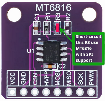
mt6816
This board config enables the MagTek MT6816 Magnetic Rotary Encoder connected to STM32F4Discovery board SPI1 this way:
STM32F4Discovery |
MT6816 |
|---|---|
3V [1] |
VCC |
GND |
GND |
PE3 |
CSN |
SPI1 MOSI (PA7) |
MOSI |
SPI1 MISO (PA6) |
MISO |
SPI1 SCK (PA5) |
SCK |
1: You need to remove the diode D3 and short-circuit the PADs in the board to get 3.3V. Be aware: although my board works fine, it could damage something that expects 3V in our board (double check).
IMPORTANT: You need to connect the HVPP (pin 2) to VCC in order to get MT6816 working in SPI mode. Just short-circuit R3 pads will work:
After compiling and flashing the firmware in our board, run qe command:
NuttShell (NSH) NuttX-12.13.0
nsh> ls /dev
/dev:
 console
 null
 qe0
 ttyS0
 zero
nsh> qe
qe_main: Hardware initialized. Opening the encoder device: /dev/qe0
qe_main: Number of samples: 0
qe_main:   1. 6546
qe_main:   2. 6620
qe_main:   3. 7384
qe_main:   4. 7808
qe_main:   5. 7900
qe_main:   6. 7984
qe_main:   7. 7989
qe_main:   8. 7993
qe_main:   9. 7998
qe_main:  10. 8008
qe_main:  11. 8052
qe_main:  12. 8064
netnsh
This is a special version of the NuttShell (nsh) configuration that is tailored to work with the STM32F4DIS-BB base board. This version derives from nsh configuration so all of the notes apply there except as noted below.
NOTES:
This example uses USART6 for the serial console. The STM32F4DIS-BB provides RS-232 drivers for USART6 and allows access via the DB9 connector on the base board. USART6 is, therefore, the more convenient UART to use for the serial console.
Networking is enabled. The STM32F4DIS-BB has an SMC LAN2870 PHY and RJ5 network connector. Support is enabled for ICMP, TCP/IP, UDP, and ARP.
SD card support is enabled. The STM32F4DIS-BB has an on-board microSD slot that should be automatically registered as the block device /dev/mmcsd0 when an SD card is present. The SD card can then be mounted by the NSH command:
nsh> mount -t /dev/mmcsd0 /mnt/sdcard
CCM memory is not included in the heap in this configuration. That is because the SD card uses DMA and if DMA memory is allocated from the CCM memory, the DMA will failure. This is an STM32 hardware limitation.
If you want to get the CCM memory back in the heap, then you can
Disable microSD support (and DMAC2 which is then no longer needed). If you reduce the clocking by a huge amount, it might be possible to use microSD without DMA. This, however, may not be possible.
Develop a strategy to manage CCM memory and DMA memory. Look at this discussion on the NuttX Wiki: https://cwiki.apache.org/confluence/display/NUTTX/STM32+CCM+Allocator
To put the CCM memory back into the heap you would need to change the following in the NuttX configuration:
CONFIG_STM32_CCMEXCLUDE=n  : Don't exclude CCM memory from the heap
CONFIG_MM_REGIONS=2        : With CCM, there will be two memory regions
nsh
Configures the NuttShell (nsh) located at apps/examples/nsh. The Configuration enables the serial interfaces on USART2. Support for builtin applications is enabled, but in the base configuration no builtin applications are selected (see NOTES below).
NOTES:
By default, this configuration uses the ARM EABI toolchain for Windows and builds under Cygwin (or probably MSYS). That can easily be reconfigured, of course.:
CONFIG_HOST_WINDOWS=y                   : Builds under Windows
CONFIG_WINDOWS_CYGWIN=y                 : Using Cygwin
CONFIG_ARM_TOOLCHAIN_GNU_EABI=y      : GNU EABI toolchain for Windows
To use this configuration with the STM32F4DIS-BB baseboard you should:
Select the STM32F4DIS-BB baseboard in the board configuration menu
Disable USART2 and select USART6 in the STM32 peripheral selection menu
Select USART6 as the serial console at 115200 8N1 in the Drivers menus
This example supports the PWM test (apps/examples/pwm) but this must be manually enabled by selecting:
CONFIG_PWM=y              : Enable the generic PWM infrastructure
CONFIG_STM32_TIM4=y       : Enable TIM4
CONFIG_STM32_TIM4_PWM=y   : Use TIM4 to generate PWM output
See also apps/examples/README.txt
Special PWM-only debug options:
CONFIG_DEBUG_PWM_INFO
This example supports the Quadrature Encode test (apps/examples/qencoder) but this must be manually enabled by selecting:
  CONFIG_EXAMPLES_QENCODER=y : Enable the apps/examples/qencoder
  CONFIG_SENSORS=y           : Enable support for sensors
  CONFIG_SENSORS_QENCODER=y          : Enable the generic Quadrature Encoder infrastructure
  CONFIG_STM32_TIM8=y        : Enable TIM8
  CONFIG_STM32_TIM2=n        : (Or optionally TIM2)
  CONFIG_STM32_TIM8_QE=y     : Use TIM8 as the quadrature encoder
  CONFIG_STM32_TIM2_QE=y     : (Or optionally TIM2)

See also apps/examples/README.tx. Special debug options::

  CONFIG_DEBUG_SENSORS
This example supports the watchdog timer test (apps/examples/watchdog) but this must be manually enabled by selecting:
  CONFIG_EXAMPLES_WATCHDOG=y : Enable the apps/examples/watchdog
  CONFIG_WATCHDOG=y          : Enables watchdog timer driver support
  CONFIG_STM32_WWDG=y        : Enables the WWDG timer facility, OR
  CONFIG_STM32_IWDG=y        : Enables the IWDG timer facility (but not both)

The WWDG watchdog is driven off the (fast) 42MHz PCLK1 and, as result,
has a maximum timeout value of 49 milliseconds.  For WWDG watchdog, you
should also add the following to the configuration file::

  CONFIG_EXAMPLES_WATCHDOG_PINGDELAY=20
  CONFIG_EXAMPLES_WATCHDOG_TIMEOUT=49

The IWDG timer has a range of about 35 seconds and should not be an issue.
USB Support (CDC/ACM device):
CONFIG_STM32_OTGFS=y          : STM32 OTG FS support
CONFIG_USBDEV=y               : USB device support must be enabled
CONFIG_CDCACM=y               : The CDC/ACM driver must be built
CONFIG_NSH_BUILTIN_APPS=y     : NSH built-in application support must be enabled
Using the USB console.
The STM32F4Discovery NSH configuration can be set up to use a USB CDC/ACM (or PL2303) USB console. The normal way that you would configure the the USB console would be to change the .config file like this:
   CONFIG_STM32_OTGFS=y           : STM32 OTG FS support
   CONFIG_USART2_SERIAL_CONSOLE=n : Disable the USART2 console
   CONFIG_DEV_CONSOLE=n           : Inhibit use of /dev/console by other logic
   CONFIG_USBDEV=y                : USB device support must be enabled
   CONFIG_CDCACM=y                : The CDC/ACM driver must be built
   CONFIG_CDCACM_CONSOLE=y        : Enable the CDC/ACM USB console.

NOTE: When you first start the USB console, you have hit ENTER a few
times before NSH starts.  The logic does this to prevent sending USB data
before there is anything on the host side listening for USB serial input.
Here is an alternative USB console configuration. The following configuration will also create a NSH USB console but this version will use /dev/console. Instead, it will use the normal /dev/ttyACM0 USB serial device for the console:
  CONFIG_STM32_OTGFS=y           : STM32 OTG FS support
  CONFIG_USART2_SERIAL_CONSOLE=y : Keep the USART2 console
  CONFIG_DEV_CONSOLE=y           : /dev/console exists (but NSH won't use it)
  CONFIG_USBDEV=y                : USB device support must be enabled
  CONFIG_CDCACM=y                : The CDC/ACM driver must be built
  CONFIG_CDCACM_CONSOLE=n        : Don't use the CDC/ACM USB console.
  CONFIG_NSH_USBCONSOLE=y        : Instead use some other USB device for the console

The particular USB device that is used is::

  CONFIG_NSH_USBCONDEV="/dev/ttyACM0"

The advantage of this configuration is only that it is easier to
bet working.  This alternative does has some side effects:

- When any other device other than /dev/console is used for a user
  interface, linefeeds (\n) will not be expanded to carriage return /
  linefeeds (\r\n).  You will need to set your terminal program to account
  for this.

- /dev/console still exists and still refers to the serial port. So
  you can still use certain kinds of debug output (see include/nuttx/debug.h, all
  of the debug output from interrupt handlers will be lost.

- But don't enable USB debug output!  Since USB is console is used for
  USB debug output and you are using a USB console, there will be
  infinite loops and deadlocks:  Debug output generates USB debug
  output which generatates USB debug output, etc.  If you want USB
  debug output, you should consider enabling USB trace
  (CONFIG_USBDEV_TRACE) and perhaps the USB monitor (CONFIG_USBMONITOR).

  See the usbnsh configuration below for more information on configuring
  USB trace output and the USB monitor.
USB OTG FS Host Support. The following changes will enable support for a USB host on the STM32F4Discovery, including support for a mass storage class driver:
  Device Drivers ->
    CONFIG_USBDEV=n          : Make sure the USB device support is disabled
    CONFIG_USBHOST=y         : Enable USB host support
    CONFIG_USBHOST_ISOC_DISABLE=y

  Device Drivers -> USB Host Driver Support
    CONFIG_USBHOST_MSC=y     : Enable the mass storage class

  System Type -> STM32 Peripheral Support
    CONFIG_STM32_OTGFS=y     : Enable the STM32 USB OTG FS block
    CONFIG_STM32_SYSCFG=y    : Needed for all USB OTF FS support

  RTOS Features -> Work Queue Support
    CONFIG_SCHED_WORKQUEUE=y : High priority worker thread support is required
    CONFIG_SCHED_HPWORK=y    :   for the mass storage class driver.

  File Systems ->
    CONFIG_FS_FAT=y          : Needed by the USB host mass storage class.

  Board Selection ->
    CONFIG_BOARDCTL=y

With those changes, you can use NSH with a FLASH pen driver as shown
belong.  Here NSH is started with nothing in the USB host slot::

  NuttShell (NSH) NuttX-x.yy
  nsh> ls /dev
  /dev:
   console
   null
   ttyS0

After inserting the FLASH drive, the /dev/sda appears and can be
mounted like this::

  nsh> ls /dev
  /dev:
   console
   null
   sda
   ttyS0
  nsh> mount -t vfat /dev/sda /mnt/stuff
  nsh> ls /mnt/stuff
  /mnt/stuff:
   -rw-rw-rw-   16236 filea.c

  And files on the FLASH can be manipulated to standard interfaces:

  nsh> echo "This is a test" >/mnt/stuff/atest.txt
  nsh> ls /mnt/stuff
  /mnt/stuff:
   -rw-rw-rw-   16236 filea.c
   -rw-rw-rw-      16 atest.txt
  nsh> cat /mnt/stuff/atest.txt
  This is a test
  nsh> cp /mnt/stuff/filea.c fileb.c
  nsh> ls /mnt/stuff
  /mnt/stuff:
   -rw-rw-rw-   16236 filea.c
   -rw-rw-rw-      16 atest.txt
   -rw-rw-rw-   16236 fileb.c

  To prevent data loss, don't forget to un-mount the FLASH drive
  before removing it:

  nsh> umount /mnt/stuff
I used this configuration to test the USB hub class. I did this testing with the following changes to the configuration (in addition to those listed above for base USB host/mass storage class support):
Drivers -> USB Host Driver Support
  CONFIG_USBHOST_HUB=y     : Enable the hub class
  CONFIG_USBHOST_ASYNCH=y  : Asynchronous I/O supported needed for hubs

System Type -> USB host configuration
  To be determined

Board Selection ->
  CONFIG_STM32F4DISCO_USBHOST_STACKSIZE=2048 (bigger than it needs to be)

RTOS Features -> Work Queue Support
  CONFIG_SCHED_LPWORK=y     : Low priority queue support is needed
  CONFIG_SCHED_LPNTHREADS=1
  CONFIG_SCHED_LPWORKSTACKSIZE=1024

NOTES:

1. It is necessary to perform work on the low-priority work queue
   (vs. the high priority work queue) because deferred hub-related
   work requires some delays and waiting that is not appropriate on
   the high priority work queue.

2. Stack usage make increase when USB hub support is enabled because
   the nesting depth of certain USB host class logic can increase.

STATUS:
2015-04-30
   Appears to be fully functional.
Using USB Device as a Mass Storage for the host computer:
 System Type  --->
     STM32 Peripheral Support  --->
         [*] OTG FS

 Device Drivers  --->
     [*] USB Device Driver Support  --->
         [*]   USB Mass storage class device  --->
             [*]   Mass storage removable

     [*] RAM Disk Support

 Board Selection  --->
     [*] Enable boardctl() interface
     [*]   Enable USB device controls

 File Systems  --->
     [*] FAT file system
     [*]   FAT upper/lower names
     [*]   FAT long file names

     [*] PROCFS File System

 Application Configuration  --->
     System Libraries and NSH Add-Ons  --->
         [*] USB Mass Storage Device Commands  --->
             (/dev/ram0) LUN1 Device Path

Compile and flash the firmware in the board as usual, then in the nsh::

 nsh> mkrd -m 0 -s 512 64

 nsh> ls /dev
 /dev:
  console
  null
  ram0
  ttyS0

 nsh> mkfatfs /dev/ram0

Connect a USB cable to STM32F4Discovery board (connector CN5) and run::

 nsh> msconn
 mcsonn_main: Creating block drivers
 mcsonn_main: Configuring with NLUNS=1
 mcsonn_main: handle=1000a550
 mcsonn_main: Bind LUN=0 to /dev/ram0
 mcsonn_main: Connected

In this moment a 33KB disk should appear in your host computer. If you
saved some file on this small disk you can now run disconnect command::

 nsh> msdis
 msdis: Disconnected

Remove the USB cable from microUSB connector and run::

 nsh> mount -t vfat /dev/ram0 /mnt

 nsh> ls /mnt
 /mnt:
  TEST.TXT

 nsh> cat /mnt/TEST.TXT
 Testing
nxlines
An example using the NuttX graphics system (NX). This example focuses on placing lines on the background in various orientations.:
CONFIG_ARM_TOOLCHAIN_GNU_EABI=y      : GNU EABI toolchain for Windows
CONFIG_LCD_LANDSCAPE=y                  : 320x240 landscape orientation
The STM32F4Discovery board does not have any graphics capability. This configuration assumes that you have connected an SD1289-based LCD as described above under “SSD1289”. NOTE: At present, it has not been proven that the STM32F4Discovery can actually drive an LCD. There are some issues with how some of the dedicated FSMC pins are used on the boards. This configuration may not be useful and may only serve as an illustration of how to build for th SSD1289 LCD.
NOTES:
As of this writing, I have not seen the LCD work!
This configured can be re-configured to use either the UG-2864AMBAG01 or UG-2864HSWEG01 0.96 inch OLEDs by adding or changing the following items in the configuration (using ‘make menuconfig’):
+CONFIG_SPI_CMDDATA=y

-CONFIG_LCD_MAXCONTRAST=1
-CONFIG_LCD_MAXPOWER=255
+CONFIG_LCD_MAXCONTRAST=255
+CONFIG_LCD_MAXPOWER=1

-CONFIG_LCD_SSD1289=y
-CONFIG_SSD1289_PROFILE1=y
+CONFIG_LCD_UG2864AMBAG01=y              : For the UG-2964AMBAG01
+CONFIG_UG2864AMBAG01_SPIMODE=3
+CONFIG_UG2864AMBAG01_FREQUENCY=3500000
+CONFIG_UG2864AMBAG01_NINTERFACES=1

-CONFIG_NX_DISABLE_1BPP=y
+CONFIG_NX_DISABLE_16BPP=y
+CONFIG_NXSTART_EXTERNINIT=y

-CONFIG_EXAMPLES_NXLINES_BGCOLOR=0x0320
-CONFIG_EXAMPLES_NXLINES_LINEWIDTH=16
-CONFIG_EXAMPLES_NXLINES_LINECOLOR=0xffe0
-CONFIG_EXAMPLES_NXLINES_BORDERWIDTH=4
-CONFIG_EXAMPLES_NXLINES_BORDERCOLOR=0xffe0
-CONFIG_EXAMPLES_NXLINES_CIRCLECOLOR=0xf7bb
-CONFIG_EXAMPLES_NXLINES_BPP=16
+CONFIG_EXAMPLES_NXLINES_BGCOLOR=0x00
+CONFIG_EXAMPLES_NXLINES_LINEWIDTH=4
+CONFIG_EXAMPLES_NXLINES_LINECOLOR=0x01
+CONFIG_EXAMPLES_NXLINES_BORDERWIDTH=2
+CONFIG_EXAMPLES_NXLINES_BORDERCOLOR=0x01
+CONFIG_EXAMPLES_NXLINES_CIRCLECOLOR=0x00
+CONFIG_EXAMPLES_NXLINES_BPP=1
+CONFIG_EXAMPLES_NXLINES_EXTERNINIT=y
There are some issues with the presentation… some tuning of the configuration could fix that. Lower resolution displays are also more subject to the “fat, flat line bug” that I need to fix someday. See https://cwiki.apache.org/confluence/pages/viewpage.action?pageId=139629474 for a description of the fat, flat line bug.
pm
This is a configuration that is used to test STM32 power management, i.e., to test that the board can go into lower and lower states of power usage as a result of inactivity. This configuration is based on the nsh2 configuration with modifications for testing power management. This configuration should provide some guidelines for power management in your STM32 application.
NOTES:
Default configuration is Cygwin under windows using the AM EABI GCC toolchain:
CONFIG_HOST_WINDOWS=y                   : Windows
CONFIG_WINDOWS_CYGWIN=y                 : Cygwin
CONFIG_ARM_TOOLCHAIN_GNU_EABI=y      : GNU EABI toolchain for Windows
CONFIG_ARCH_CUSTOM_PMINIT and CONFIG_ARCH_IDLE_CUSTOM are necessary parts of the PM configuration:
CONFIG_ARCH_CUSTOM_PMINIT=y
CONFIG_ARCH_CUSTOM_PMINIT moves the PM initialization from arch/arm/src/common/stm32/stm32_pminitialize_m3m4_v1.c to boards/arm/stm32f1/stm3210e-eval/src/stm32_pm.c. This allows us to support board-specific PM initialization.:
CONFIG_ARCH_IDLE_CUSTOM=y
The bulk of the PM activities occur in the IDLE loop. The IDLE loop is special because it is what runs when there is no other task running. Therefore when the IDLE executes, we can be assure that nothing else is going on; this is the ideal condition for doing reduced power management.
The configuration CONFIG_ARCH_IDLE_CUSTOM allows us to “steal” the normal STM32 IDLE loop (of arch/arm/src/common/stm32/stm32_idle_m3m4_v1.c) and replace this with our own custom IDLE loop (at boards/arm/stm32f1/stm3210e-eval/src/up_idle.c).
Here are some additional things to note in the configuration:
CONFIG_PM_BUTTONS=y
CONFIG_PM_BUTTONS enables button support for PM testing. Buttons can drive EXTI interrupts and EXTI interrupts can be used to wakeup for certain reduced power modes (STOP mode). The use of the buttons here is for PM testing purposes only; buttons would normally be part the application code and CONFIG_PM_BUTTONS would not be defined.:
CONFIG_RTC_ALARM=y
The RTC alarm is used to wake up from STOP mode and to transition to STANDBY mode. This used of the RTC alarm could conflict with other uses of the RTC alarm in your application.
posix_spawn
This configuration directory, performs a simple test os the posix_spawn interface using apps/examples/posix_spawn.
NOTES:
Default toolchain:
CONFIG_HOST_WINDOWS=y                   : Builds under windows
CONFIG_WINDOWS_CYGWIN=y                 : Using Cygwin and
CONFIG_ARM_TOOLCHAIN_GNU_EABI=y      : Generic ARM EABI toolchain for Windows
By default, this project assumes that you are NOT using the DFU bootloader.
pseudoterm
This is a configuration to test the Pseudo Terminal support for NuttX.
To test it you will need two USB/Serial dongles. The first dongle as usual will be used to main NSH console port in USART2 (PA2 and PA3) and the second dongle you will connect to UART3 (PB10 and PB11).
In the main NSH console (in USART2) type: “pts_test &”. It will create a new console in UART3. Just press ENTER and start typing commands on it.
sporadic
This is an NSH configuration that includes apps/testing/ostest as a builtin. The sporadic scheduler is enabled and the purpose of this configuration is to investigate an error in that scheduler. See Issue 2035. The serial console is on USART6.
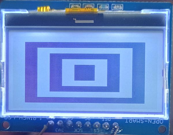
st7567
Configures the board to support a ST7567 monochromatic LCD like the OPEN-SMART 1.8INCH LCD.
Connect the STM32F4Discovery board to ST7567 LCD this way:
STM32F4Discovery |
ST7567 LCD |
|---|---|
GND |
GND |
3V [1] |
3V3 |
SPI1 MOSI (PA7) |
SDI |
SPI1 SCK (PA5) |
SCK |
PB8 |
DC |
SPI1 CS (PB7) |
CS |
PB6 |
RST |
GND |
LED |
1: You need to remove the diode D3 and short-circuit the PADs in the board to get 3.3V. Be aware: although my board works fine, it could damage something that expects 3V in our board (double check).
After compiling and flashing the firmware in our board, run fb command.
NuttShell (NSH) NuttX-12.12.0
nsh> ?
help usage:  help [-v] [<cmd>]

    .           cp          expr        mount       kill        uname
    [           cmp         false       mv          pkill       umount
    ?           dirname     fdinfo      pidof       sleep       unset
    alias       df          free        printf      usleep      uptime
    unalias     dmesg       help        ps          source      watch
    basename    echo        hexdump     pwd         test        xd
    break       env         ls          rm          time        wait
    cat         exec        mkdir       rmdir       true
    cd          exit        mkrd        set         truncate

  Builtin Apps:
  dd       fb       hello    nsh      sh
nsh> fb
VideoInfo:
      fmt: 0
      xres: 128
     yres: 64
  nplanes: 1
PlaneInfo (plane 0):
    fbmem: 0x10000a98
    fblen: 1024
   stride: 16
  display: 0
      bpp: 1
Mapped FB: 0x10000a98
 0: (  0,  0) (128, 64)
 1: ( 11,  5) (106, 54)
 2: ( 22, 10) ( 84, 44)
 3: ( 33, 15) ( 62, 34)
 4: ( 44, 20) ( 40, 24)
 5: ( 55, 25) ( 18, 14)
Test finished
nsh>
You should see this image:
testlibcxx
This is a configuration for testing lib++. See the section above entitled “Testing LLVM LIBC++ with NuttX” for detailed information about this configuration.
rgbled
Alan Carvalho de Assis has used the STM32F4-Discovery to drive an RGB LED using PWM output. The external RGB connected this way:
R = TIM1 CH1 on PE9
G = TIM2 CH2 on PA1
B = TIM3 CH3 on PB0
as described about in the section “RGB LED Driver”.
This configuration uses the example at apps/examples/rgbled to drive the external RGB LED>
rndis
This is a board configuration to demonstrate how to use Ethernet-over-USB, in this case using the RNDIS protocol. Using it you can get access to your board using Telnet or you can use transfer file to it. Both steps will be explained below.
Your board will be get IP address from a DHCP server. If you want to use a fixed IP instead using DHCP, you need to disable the DHCP Client and set up its IP. For more info watch: www.youtube.com/watch?v=8noH8v7xNgs
You can access the board’s NuttShell just typing in the Linux terminal:
$ telnet 10.0.0.2
You should see something like this:
Trying 10.0.0.2...
Connected to 10.0.0.2.
Escape character is '^]'.

NuttShell (NSH)
nsh>
This board configuration has support to RAMDISK because we need a writable filesystem to get files from the computer. Then you need to create first a RAMDISK and mount it using these steps:
nsh> mkrd 64
nsh> mkfatfs /dev/ram0
nsh> mount -t vfat /dev/ram0 /mnt
Open a new Linux terminal and start a webserver, Python one embedded:
$ python -m SimpleHTTPServer
It will create a webserver serving in the port 8000 and will share files in the current directory where it was executed.
Then in the NuttShell you can run these commands to download a small file:
nsh> cd /mnt
nsh> wget http://10.0.0.1:8000/test.txt
nsh> ls -l
/mnt:
 -rw-rw-rw-      23 test.txt
This configuration also supports:
An NFS file system client. Relevant configuration options:
CONFIG_NFS=y
CONFIG_NFS_STATISTICS=y
Loadable ELF modules:
CONFIG_SYMTAB_ORDEREDBYNAME=y
CONFIG_ELF=y
CONFIG_EXAMPLES_HELLO=m
CONFIG_LIBC_EXECFUNCS=y
CONFIG_NSH_FILE_APPS=y
CONFIG_NSH_SYMTAB=y
CONFIG_NSH_SYMTAB_ARRAYNAME="g_symtab"
CONFIG_NSH_SYMTAB_COUNTNAME="g_nsymbols"

Further, the configuration assumes that executable files reside on the
remotely mounted file system:

CONFIG_LIBC_ENVPATH=y
CONFIG_PATH_INITIAL="/mnt/nfs/bin"
3 ‘ping’ support:
CONFIG_NET_ICMP_SOCKET=y
CONFIG_SYSTEM_PING=y
usbnsh
This is another NSH example. If differs from other ‘nsh’ configurations in that this configurations uses a USB serial device for console I/O. Such a configuration is useful on the stm32f4discovery which has no builtin RS-232 drivers.
NOTES:
By default, this configuration uses the ARM EABI toolchain for Windows and builds under Cygwin (or probably MSYS). That can easily be reconfigured, of course.:
CONFIG_HOST_WINDOWS=y                   : Builds under Windows
CONFIG_WINDOWS_CYGWIN=y                 : Using Cygwin
CONFIG_ARM_TOOLCHAIN_GNU_EABI=y      : GNU EABI toolchain for Windows
This configuration does have USART2 output enabled and set up as the system logging device:
CONFIG_SYSLOG_CHAR=y               : Use a character device for system logging
CONFIG_SYSLOG_DEVPATH="/dev/ttyS0" : USART2 will be /dev/ttyS0
However, there is nothing to generate SYSLOG output in the default configuration so nothing should appear on USART2 unless you enable some debug output or enable the USB monitor.
NOTE: Using the SYSLOG to get debug output has limitations. Among those are that you cannot get debug output from interrupt handlers. So, in particularly, debug output is not a useful way to debug the USB device controller driver. Instead, use the USB monitor with USB debug off and USB trace on (see below).
Enabling USB monitor SYSLOG output. If tracing is enabled, the USB device will save encoded trace output in in-memory buffer; if the USB monitor is enabled, that trace buffer will be periodically emptied and dumped to the system logging device (USART2 in this configuration):
CONFIG_USBDEV_TRACE=y                   : Enable USB trace feature
CONFIG_USBDEV_TRACE_NRECORDS=128        : Buffer 128 records in memory
CONFIG_NSH_USBDEV_TRACE=n               : No builtin tracing from NSH
CONFIG_USBMONITOR=y              : Enable the USB monitor daemon
CONFIG_USBMONITOR_STACKSIZE=2048 : USB monitor daemon stack size
CONFIG_USBMONITOR_PRIORITY=50    : USB monitor daemon priority
CONFIG_USBMONITOR_INTERVAL=2     : Dump trace data every 2 seconds

CONFIG_USBMONITOR_TRACEINIT=y    : Enable TRACE output
CONFIG_USBMONITOR_TRACECLASS=y
CONFIG_USBMONITOR_TRACETRANSFERS=y
CONFIG_USBMONITOR_TRACECONTROLLER=y
CONFIG_USBMONITOR_TRACEINTERRUPTS=y
By default, this project assumes that you are NOT using the DFU bootloader.
Using the Prolifics PL2303 Emulation
You could also use the non-standard PL2303 serial device instead of the standard CDC/ACM serial device by changing:
CONFIG_CDCACM=n               : Disable the CDC/ACM serial device class
CONFIG_CDCACM_CONSOLE=n       : The CDC/ACM serial device is NOT the console
CONFIG_PL2303=y               : The Prolifics PL2303 emulation is enabled
CONFIG_PL2303_CONSOLE=y       : The PL2303 serial device is the console
winbuild
This is a version of the apps/example/ostest, but configure to build natively in the Windows CMD shell.
NOTES:
The beginnings of a Windows native build are in place but still not full usable as of this writing. The windows native build logic is currently separate and must be started by:
make -f Win.mk
This build:
Uses all Windows style paths
Uses primarily Windows batch commands from cmd.exe, with
A few extensions from GNUWin32 (or MSYS is you prefer)
In this build, you cannot use a Cygwin or MSYS shell. Rather the build must be performed in a Windows console. Here is a better shell than than the standard issue, CMD.exe shell: ConEmu which can be downloaded from: http://code.google.com/p/conemu-maximus5/
CONFIG_HOST_WINDOWS=y                   : Windows
CONFIG_WINDOWS_NATIVE=y                 : Native Windows environment
CONFIG_ARM_TOOLCHAIN_GNU_EABI=y      : GNU EABI toolchain for Windows
Build Tools. The build still relies on some Unix-like commands. I use the GNUWin32 tools that can be downloaded from http://gnuwin32.sourceforge.net/. The MSYS tools are probably also a option but are likely lower performance since they are based on Cygwin 1.3.
Host Compiler: I use the MingW compiler which can be downloaded from http://www.mingw.org/. If you are using GNUWin32, then it is recommended the you not install the optional MSYS components as there may be conflicts.
HX711
HX711 is a precision 24-bit analog-to-digital converter (ADC) designed for weigh scales and industrial control applications. It interfaces load cells via a simple two-wire serial interface (clock and data) and provides high-resolution digital weight measurements.
Enable the following options using ``make menuconfig``:
CONFIG_ADC=y
CONFIG_ANALOG=y
CONFIG_ADC_HX711=y
CONFIG_EXAMPLES_HX711=y
Wiring:
Connect the HX711 to the STM32F4 board using the following pins:
HX711 |
PIN |
|---|---|
SCK |
PB1 |
DT |
PB2 |
NSH usage:
NuttShell (NSH) NuttX-12.10.0
nsh> hx711 -D
Current settings for: /dev/hx711_0
average.............: 1
channel.............: a
gain................: 128
value per unit......: 0
nsh> hx711 -v 813 -t 10
Taring with *float*g precision
nsh> hx711 -r 10
-2
0
0
-1
-3
-3
-2
-2
-4
-4
For more details, refer to the official HX711 NuttX documentation.
nxscope_cdcacm
Configuration demonstrating NxScope stream over CDC-ACM interface. See nxscope NxScope library example and NxScope Library for more details.