stm32f401rc-rs485
This page discusses issues unique to NuttX configurations for the NuttX STM32F4-RS485 development board.
Board information
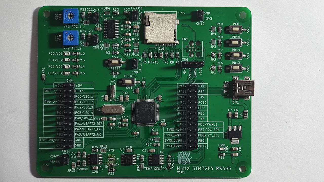
This board was release on NuttX International Workshop 2023 and developed based on STM32F401RCT6 microcontroller.
- STM32F401RCT6 microcontroller features:
Arm 32-bit Cortex®-M4 CPU with FPU
256 Kbytes of Flash memory
64 Kbytes of SRAM
Serial wire debug (SWD) & JTAG interfaces
Up to 81 I/O ports with interrupt capability
Up to 11 communication interfaces
Up to 3 I2C interfaces
Up to 3 USARTs
Up to 4 SPIs
SDIO interface
USB 2.0 full-speed device/host/OTG controller with on-chip PHY
The board features:
Digital I2C Temperature Sensor (TMP75)
2K bits (256x8) I2C EEPROM
On-board RS485 Transceiver
Two Analog Input Stages with Amplifier Buffer
Two Analog Output Stages with Amplifier Buffer
MicroSD Connector supporting 1 or 4-bit bus
Four User LEDs
Four User Buttons
USB for DFU (Device Firmware Update) and USB device functionality, as well as powering the board
Onboard voltage regulator from 5V to 3.3V
SWD Pins for use as STLink (Pin header) and TC2030-IDC 6-Pin Tag-Connect Plug-of-Nails™ Connector
Crystal for HS 8MHz
Crystal for RTC 32.768KHz
Board documentation: https://github.com/lucaszampar/NuttX_STM32F4_RS485_DevBoard
As F4 series have a USB DFuSe-capable BootROM [AN2606], the board can be flashed via dfu-util over USB, or via stm32flash over UART without any debuggers.
LEDs
The STM32F4-RS485 has 4 software controllable LEDs.
LED |
PINS |
|---|---|
LED_1 |
PC0 |
LED_2 |
PC1 |
LED_4 |
PC2 |
LED_5 |
PC3 |
UARTs
The STM32F4-RS485 has 1 USART available for user.
USART6
UART/USART |
PINS |
|---|---|
TX |
PC6 [1] |
RX |
PC7 |
CK |
PA8 |
[1] Warning you make need to reverse RX/TX on some RS-232 converters
SDCard support
The STM32F4-RS485 has 1 SDCard slot connected as below:
SDIO |
PINS |
|---|---|
SDIO_D0 |
PC8 |
SDIO_D1 |
PC9 |
SDIO_D2 |
PC10 |
SDIO_D3 |
PC11 |
SDIO_DK |
PC12 |
EEPROM
The STM32F4-RS485 development board has serial EEPROM HX24LC02B, with 2k bits (256x8) and internally organized with 32 pages of 8 bytes each. It is connected through I2C as below:
I2C |
PINS |
|---|---|
SDA |
PB7 |
SCL |
PB8 |
Users can enable EERPOM support on STM32F4-RS485 by following below configuration:
Configure basic nsh:
./tools/configure.sh -l stm32f401rc-rs485:nsh
Enable the following configs:
CONFIG_DEV_ZERO=y
CONFIG_EEPROM=y
CONFIG_FS_PROCFS=y
CONFIG_I2C=y
CONFIG_I2C_EE_24XX=y
CONFIG_STM32_I2C1=y
Build and flash the STM32F4-RS485.
Use dd command to write and read data from EEPROM as below:
nsh> dd if=/dev/zero of=/dev/eeprom
nsh: dd: write failed: 1
nsh> dd if=/dev/console of=/dev/eeprom bs=1 count=4
(type "Hello")
nsh> dd if=/dev/eeprom of=/dev/console bs=4 count=1
Hellonsh>
Temperature Sensor
The STM32F4-RS485 development board has a temperature sensor TMP75 (compatible with LM75) connected through I2C as below:
I2C |
PINS |
|---|---|
SDA |
PB7 |
SCL |
PB8 |
RS485 Transceiver
The STM32F4-RS485 development board has a half-duplex RS-485 transceiver, the BL3085B it is connected through USART2 as below:
USART2 |
PINS |
|---|---|
USART2_RX |
RO |
USART2_RTS |
DE, /RE |
USART2_RX |
DI |
A/D Converter
The STM32F4-RS485 development board has two Analog to Digital converters with Amplifier Buffer (1COS724SR) and connected as below:
PWM |
PINS |
|---|---|
PWM_1 |
PB6 |
PWM_2 |
PA6 |
D/C Converter
The STM32F4-RS485 development board has two Digital to Analog converters with Amplifier Buffer (1COS724SR) and connected as below:
ADC |
PINS |
|---|---|
ADC_1 |
PA0 |
ADC_2 |
PA4 |
Configurations
Each stm32f401rc-rs485 configuration is maintained in a sub-directory and can be selected as follow:
tools/configure.sh stm32f401rc-rs485:<subdir>
Where <subdir> is one of the following:
Configuration Directories
nsh
Configures the NuttShell (nsh) located at apps/examples/nsh. This configuration enables a serial console on USART6.
usbnsh
Configures the NuttShell (nsh) located at apps/examples/nsh. This configuration enables a serial console over USB.
After flashing and reboot your board you should see in your dmesg logs:
[ 2638.948089] usb 1-1.4: new full-speed USB device number 16 using xhci_hcd
[ 2639.054432] usb 1-1.4: New USB device found, idVendor=0525, idProduct=a4a7, bcdDevice= 1.01
[ 2639.054437] usb 1-1.4: New USB device strings: Mfr=1, Product=2, SerialNumber=3
[ 2639.054438] usb 1-1.4: Product: CDC/ACM Serial
[ 2639.054440] usb 1-1.4: Manufacturer: NuttX
[ 2639.054441] usb 1-1.4: SerialNumber: 0
[ 2639.074861] cdc_acm 1-1.4:1.0: ttyACM0: USB ACM device
[ 2639.074886] usbcore: registered new interface driver cdc_acm
[ 2639.074887] cdc_acm: USB Abstract Control Model driver for USB modems and ISDN adapters
You may need to press ENTER 3 times before the NSH show up.
sdcard
Configures the NuttShell (nsh) and enables SD card support. The stm32f401rc-rs485 has an onboard microSD slot that should be automatically registered as the block device /dev/mmcsd0 when an SD card is present. The SD card can then be mounted by the NSH commands:
nsh> mount -t procfs /proc
nsh> mount -t vfat /dev/mmcsd0 /mnt
modbus_slave
Configures the NuttShell (nsh) and enables modbus in slave mode. This configuration enables a serial console on USART6. The RS-485 is connected to USART2. Follow below procedure to use modbus test application, you will need a USB to RS-485 converter to connect the board to a PC via RS-485.
NuttShell configuration:
Run modbus application at NSH:
nsh> modbus -help
USAGE: modbus [-d|e|s|q|h]

Where:
  -d : Disable protocol stack
  -e : Enable the protocol stack
  -s : Show current status
  -q : Quit application
  -h : Show this information

nsh> modbus -e
PC Configuration:
Download and install mbpoll application:
sudo apt install mbpoll
Check which TTY USB port is being used by you USB to RS-485 converter:
sudo dmesg
[99846.668209] usb 1-1.3: Product: USB Serial
[99846.676313] ch341 1-1.3:1.0: ch341-uart converter detected
[99846.677454] usb 1-1.3: ch341-uart converter now attached to ttyUSB1
Run the mbpoll as below:
mbpoll -a 10 -b 38400 -t 3 -r 1000 -c 4 /dev/ttyUSB1 -R
At PC terminal you will see the mbpoll application receiving the random values generated by STM32F401RC-RS485 and transmitted over RS-485:
mbpoll 1.0-0 - FieldTalk(tm) Modbus(R) Master Simulator
Copyright © 2015-2019 Pascal JEAN, https://github.com/epsilonrt/mbpoll
This program comes with ABSOLUTELY NO WARRANTY.
This is free software, and you are welcome to redistribute it
under certain conditions; type 'mbpoll -w' for details.

Protocol configuration: Modbus RTU
Slave configuration...: address = [10]
                        start reference = 1000, count = 4
Communication.........: /dev/ttyUSB1,      38400-8E1
                        t/o 1.00 s, poll rate 1000 ms
Data type.............: 16-bit register, input register table
-- Polling slave 10... Ctrl-C to stop)
[1000]:  58080 (-7456)
[1001]:  0
[1002]:  0
[1003]:  0
-- Polling slave 10... Ctrl-C to stop)
[1000]:  6100
[1001]:  0
[1002]:  0
[1003]:  0
-- Polling slave 10... Ctrl-C to stop)
[1000]:  51010 (-14526)
[1001]:  0
[1002]:  0
[1003]:  0
-- Polling slave 10... Ctrl-C to stop)
[1000]:  12528
[1001]:  0
[1002]:  0
[1003]:  0
modbus_master
Configures the NuttShell (nsh) and enables modbus in master mode. This configuration enables a serial console on USART6. The RS-485 is connected to USART2. Follow below procedure to use modbusmaster test application, you will need a USB to RS-485 converter to connect the board to a PC via RS-485.
PC Configuration:
Download and install diagslave application from https://www.modbusdriver.com/diagslave.html.
Check which TTY USB port is being used by you USB to RS-485 converter:
sudo dmesg
[99846.668209] usb 1-1.3: Product: USB Serial
[99846.676313] ch341 1-1.3:1.0: ch341-uart converter detected
[99846.677454] usb 1-1.3: ch341-uart converter now attached to ttyUSB1
Run the diagslave as below:
sudo diagslave -a 10 -b 38400 /dev/ttyUSB1
At PC terminal you will see the diagslave application listening to address 10, notice that this address is configurable via MODBUSMASTER_SLAVEADDR:
diagslave 3.4 - FieldTalk(tm) Modbus(R) Diagnostic Slave Simulator
Copyright (c) 2002-2021 proconX Pty Ltd
Visit https://www.modbusdriver.com for Modbus libraries and tools.

Protocol configuration: Modbus RTU, frame tolerance = 0ms
Slave configuration: address = 10, master activity t/o = 3.00s
Serial port configuration: /dev/ttyUSB1, 38400, 8, 1, even

Server started up successfully.
Listening to network (Ctrl-C to stop)
Slave  10: readHoldingRegisters from 2, 1 references
.......
NuttShell configuration:
Run modbusmaster application at NSH:
NuttShell (NSH) NuttX-12.4.0
nsh> modbusmaster
Initializing modbus master...
Creating poll thread.
Sending 100 requests to slave 10
mbmaster_main: Exiting poll thread.
Modbus master statistics:
Requests count:  100
Responses count: 100
Errors count:    0
Deinitializing modbus master...
The application modbusmaster will send 100 requests, you can check on diagslave:
Server started up successfully.
Listening to network (Ctrl-C to stop)
Slave  10: readHoldingRegisters from 2, 1 references
Slave  10: readHoldingRegisters from 2, 1 references
Slave  10: readHoldingRegisters from 2, 1 references
Slave  10: readHoldingRegisters from 2, 1 references
Slave  10: readHoldingRegisters from 2, 1 references
Slave  10: readHoldingRegisters from 2, 1 references
Slave  10: readHoldingRegisters from 2, 1 references
lm75
Configures the NuttShell (nsh) over USB Serial (check usbserial configuration) and enables temperature sensor LM75. NSH commands:
nsh> lm75 -help
Usage: temp [OPTIONS]
  [-n count] selects the samples to collect.  Default: 1 Current: 100
  [-h] shows this message and exits
nsh> lm75 -n 3
30.13 degrees Celsius
30.13 degrees Celsius
30.13 degrees Celsius
adc
Configures the NuttShell (nsh) over USB Serial (check usbserial configuration) and enables ADC 1 on channels 0 and 4. NSH commands:
nsh> adc -h
Usage: adc [OPTIONS]

Arguments are "sticky".  For example, once the ADC device is
specified, that device will be reused until it is changed.

"sticky" OPTIONS include:
  [-p devpath] selects the ADC device.  Default: /dev/adc0 Current: /dev/adc0
  [-n count] selects the samples to collect.  Default: 1 Current: 0
  [-h] shows this message and exits
nsh> adc -n 2
adc_main: g_adcstate.count: 2
adc_main: Hardware initialized. Opening the ADC device: /dev/adc0
Sample:
1: channel: 0 value: 2684
Sample:
1: channel: 4 value: 2682
Currently there is a bug that causes the application to always read the same value for channel 0 and 4. If you want to read the value from channel 2, you will need to enable the config “ADC1 Scan Mode”.
dac
Configures the NuttShell (nsh) over USB Serial (check usbserial configuration) and enables PWM 3 on channel 1. Use pwm command on NSH to change dutty cycle, frequency and duration, use dac_out_2 to measure the output voltage. NSH commands:
nsh> pwm -h
Usage: pwm [OPTIONS]

Arguments are "sticky".  For example, once the PWM frequency is
specified, that frequency will be reused until it is changed.

"sticky" OPTIONS include:
  [-p devpath] selects the PWM device.  Default: /dev/pwm0 Current: NONE
  [-f frequency] selects the pulse frequency.  Default: 100 Hz Current: 100 Hz
  [-d duty] selects the pulse duty as a percentage.  Default: 50 % Current: 50 %
  [-t duration] is the duration of the pulse train in seconds.  Default: 5 Current: 5
  [-h] shows this message and exits
nsh> pwm -d 50 -t 3
pwm_main: starting output with frequency: 50 duty: 00007fff
pwm_main: stopping output
qencoder
Configures the NuttShell (nsh) over USB Serial (check usbserial configuration) and enables Timer 3 on channels 1 and 2 to handle Quadrature Encoder. NSH commands:
nsh> qe -help

Usage: qe [OPTIONS]

OPTIONS include:
  [-p devpath] QE device path
  [-n samples] Number of samples
  [-t msec]    Delay between samples (msec)
  [-r]         Reset the position to zero
  [-h]         Shows this message and exits
  nsh> qe -p /dev/qe0 -n 5 -t 100 -r
  nsh: qe: too many arguments
  qe_main: Hardware initialized. Opening the encoder device: /dev/qe0
  qe_main: Resetting the count...
  qe_main: Number of samples: 5
  qe_main:   1. 0
  qe_main:   2. 0
  qe_main:   3. 4
  qe_main:   4. 2
  qe_main:   5. 2
  Terminating!
rndis
Configures the NuttShell (nsh), enables a serial console on USART6 and enables RNDIS over USB. NSH commands:
nsh> mount -t procfs /proc
nsh> ping -h

Usage: ping [-c <count>] [-i <interval>] [-W <timeout>] [-s <size>] <hostname>
ping -h

Where:
<hostname> is either an IPv4 address or the name of the remote host
that is requested the ICMPv4 ECHO reply.
-c <count> determines the number of pings.  Default 10.
-i <interval> is the default delay between pings (milliseconds).
Default 1000.
-W <timeout> is the timeout for wait response (milliseconds).
Default 1000.
-s <size> specifies the number of data bytes to be sent.  Default 56.
-h shows this text and exits.

nsh> ping 10.42.0.1
PING 10.42.0.1 56 bytes of data
56 bytes from 10.42.0.1: icmp_seq=0 time=0.0 ms
56 bytes from 10.42.0.1: icmp_seq=1 time=0.0 ms
...
10 packets transmitted, 10 received, 0% packet loss, time 10100 ms
rtt min/avg/max/mdev = 0.000/0.000/0.000/0.000 ms
usbmsc
Configures the NuttShell (nsh), enables a serial console on USART6 and enables USB Mass Storage. NSH commands:
nsh> msconn
mcsonn_main: Creating block drivers
mcsonn_main: Configuring with NLUNS=1
mcsonn_main: handle=0x20004c10
mcsonn_main: Bind LUN=0 to /dev/mmcsd0
mcsonn_main: Connected

nsh> msdis
hcs04
Configures the NuttShell (nsh) over USB Serial (check usbserial configuration) and enables ultrasonic sensor HC-SR04:
nsh> cat /dev/dist0
6241 --> value
6227
6241
6255
You can convert the value using following:
Convert to cm: value/58
Convert to inches: value/148
ssd1309
This config is used to enable support to the transparent OLED display powered by SSD1309. The resolution of this display is 128x64 (although the effective view is 128x56).
You can wire the display to your board this way:
OLED |
PINS |
|---|---|
CS |
PB7 |
DC |
PB8 |
RESET |
PB6 |
SDA |
PA7 |
SCK |
PA5 |
The board profile configures the NSH over USB and you can use the fb command to test:
NuttShell (NSH) NuttX-12.5.1
nsh> fb
VideoInfo:
      fmt: 0
     xres: 128
     yres: 64
  nplanes: 1
PlaneInfo (plane 0):
    fbmem: 0x200034f8
    fblen: 1024
   stride: 16
  display: 0
      bpp: 1
Mapped FB: 0x200034f8
 0: (  0,  0) (128, 64)
 1: ( 11,  5) (106, 54)
 2: ( 22, 10) ( 84, 44)
 3: ( 33, 15) ( 62, 34)
 4: ( 44, 20) ( 40, 24)
 5: ( 55, 25) ( 18, 14)
Test finished
nsh>
telnetd
Configures the NuttShell (nsh), enables a serial console on USART6, enables RNDIS over USB and enables Device Configuration over Telnet. NSH commands:
nsh> mount -t procfs /proc
nsh> ifcong
Get the ip address assigned to eth0 and convert to hexadecimal, for example 192.168.1.2 becomes 0xC0A80102, than configure CONFIG_NETINIT_IPADDR and CONFIG_EXAMPLES_TELNETD_IPADDR, also configure the router address, in this example it would be 0xC0A80101. After these changes rebuild and load the new firmware on your board:
nsh> mount -t procfs /proc
nsh> telnetd
At your host PC, telnet to IP address for the board:
$ telnet 192.168.01.02
Now you will be able to access the Device Configuration over Telnet:
Device Configuration over Telnet
You can add functions to setup your device
Type '?' and press <enter> for help
cfg> ?
Available commands:
help, ?   - show help
reset     - reset the board
exit      - exit shell
max7219
Configures the NuttShell (nsh) over USB Serial (check usbserial configuration) and enables LCD driver with MAX7219 for 8x8 LED matrix:
NuttShell (NSH) NuttX-12.5.1
nsh>
nsh> nxhello
nxhello_main: NX handle=0x20005420
nxhello_main: Set background color=0
nxhello_listener: Connected
nxhello_main: Screen resolution (32,8)
nxhello_hello: Position (3,0)
nxhello_main: Disconnect from the server
nsh>
MAX7219 |
PINS |
|---|---|
CS |
PC4 |
DIN |
PA7 |
Clk |
PA5 |
As this LED matrix can be combined either horizontally or vertically, you can configure this using menuconfig:
Number of 8x8 LEDs matrices in the horizontal (width)
Number of 8x8 LEDs matrices in the vertical (height)
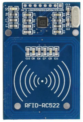
mfrc522
Configures the NuttShell (nsh) over USB Serial (check usbserial configuration) and enables RFID driver with MFRC522:
nsh> rfid_readuid
Trying to READ: Card is not present!
Trying to READ: Card is not present!
Trying to READ: RFID CARD UID = 0x3DB3F169
MFRC522 |
PINS |
|---|---|
SCK |
PA5 |
MISO |
PA6 |
MOSI |
PA7 |
CS |
PC5 |
The board used is based on MFRC522 NXP IC that supports contactless communication at 13.56 MHz and ISO/IEC 14443 A/MIFARE and NTAG.
bmp280
Configures the NuttShell (nsh) over USB Serial (check usbserial configuration) and enables BMP280 Digital Pressure Sensor. BMP280 has an I2C address that can be configure by SDO. Connecting SDO to GND results in slave address 0x76, connection it to VDD results in slave address 0x77. This can be configured by enabling BMP280_I2C_ADDR_76 or BMP280_I2C_ADDR_77. This configuration uses I2C1 and slave address 0x77.
SENSOR |
PINS |
|---|---|
SDA |
PA7 |
SCK |
PB8 |
NSH commands:
NuttShell (NSH) NuttX-12.6.0-RC1
nsh> bmp280
Absolute pressure [hPa] = 911.400024
Temperature [C] = 26.110001
nsh> bmp280
Absolute pressure [hPa] = 932.650024
Temperature [C] = 24.490000
There is a known issue where every time the sensor is initialized, the first measurement is wrong, please check https://github.com/apache/nuttx/issues/12421 for the latest updates on this issue.
lcd1602
This configuration sets up the NuttShell (NSH) interface over USB Serial (refer to the usbserial configuration for details). It also enables I2C1 and the driver for an alphanumeric/segment LCD. Specifically, the setup supports a 16x2 LCD screen based on the HD44780 controller, which is interfaced using an I2C adapter known as the LCD Backpack, utilizing the PCF8574 chip.
LCD |
PINS |
|---|---|
SDA |
PA7 |
SCK |
PB8 |
NSH commands:
nsh> slcd "Hello NuttX"
Opening /dev/slcd0 for read/write access
Attributes:
  rows: 2 columns: 16 nbars: 0
  max contrast: 0 max brightness: 1
Clear screen
WRITING:
0000: 1b5b46                                                            .[F
Set brightness to 1
Print [Hello NuttX]
WRITING:
0000: 1b5b471b5b30304c1b5b4548656c6c6f 204e75747458                     .[G.[00L.[EHello  NuttX
Test complete
nsh>
ws2812
This configuration sets up the NuttShell (NSH) interface over USB Serial (refer to the usbserial configuration for details). It also enables the driver for an addressable LED WS2812 and the SPI1. The MOSI pin from SPI must be connected to DIN on WS2812 module and the number of LEDs can be configured using CONFIG_WS2812_LED_COUNT.
WS2812 |
PINS |
|---|---|
DIN |
PA7 |
NSH commands:
NuttShell (NSH) NuttX-12.7.0-RC0
nsh> ws2812
bmp180
The BMP180 is a digital barometric pressure sensor that provides pressure and temperature readings over I2C. It is commonly used in weather monitoring, altimetry, and embedded sensor applications.
This guide describes how to configure and use the BMP180 sensor in NuttX with two available drivers: the regular driver and the UORB driver. It also includes example NSH commands and the required hardware pin configuration.
Initial Setup
Ensure the NuttShell (NSH) is configured either over USB Serial (configure usbnsh) or via UART
(configure nsh) to perform board-level configuration.
Regular Driver
This driver offers basic access to the BMP180 sensor values directly through a command-line utility.
Enable the following options using ``make menuconfig``:
CONFIG_ARCH_BOARD_COMMON=y
CONFIG_STM32_I2C1=y
CONFIG_EXAMPLES_BMP180=y
CONFIG_SENSORS=y
CONFIG_SENSORS_BMP180=y
NSH usage:
NuttShell (NSH) NuttX-12.8.0
nsh> bmp180
Pressure value = 93592
Pressure value = 93591
Pressure value = 93595
This output shows raw pressure values (in Pascals).
UORB Driver
This driver integrates the sensor into the UORB publish/subscribe system. It supports high-level features such as scheduling and multi-sensor handling.
Enable the following options using ``make menuconfig``:
CONFIG_ARCH_BOARD_COMMON=y
CONFIG_STM32_I2C1=y
CONFIG_LIBC_FLOATINGPOINT=y
CONFIG_SENSORS=y
CONFIG_SENSORS_BMP180=y
CONFIG_SENSORS_BMP180_UORB=y
CONFIG_SYSTEM_SENSORTEST=y
CONFIG_SYSTEM_SENSORTEST_PROGNAME="sensor"
CONFIG_SCHED_WORKQUEUE=y
CONFIG_SCHED_LPWORK=y
NSH usage:
NuttShell (NSH) NuttX-12.8.0
nsh> sensor baro0
SensorTest: Test /dev/uorb/sensor_baro0 with interval(1000000us), latency(0us)
baro0: timestamp:2170620000 value1:935.92 value2:224.00
baro0: timestamp:2171630000 value1:935.92 value2:224.00
baro0: timestamp:2172640000 value1:935.89 value2:224.00
value1corresponds to pressure in hPa (hectopascals).value2corresponds to temperature in tenths of degrees Celsius (e.g., 224.00 = 22.4°C).
Connect the BMP180 sensor to the STM32 board using the I2C interface.
SENSOR |
PIN |
|---|---|
SDA |
PB7 |
SCL |
PB8 |
ST7735
This example shows how to bring up and use a ST7735-based TFT LCD display in NuttX.
How to add support for the ST7735 display to a new board in NuttX:
LCD Initialization: Implement LCD initialization/uninitialization in stm32_lcd_st7735.c to handle the display. You can copy this from another board that supports ST7735.
Update CMakeLists.txt and Make.defs: Add stm32_lcd_st7735.c if CONFIG_LCD_ST7735 is enabled.
SPI Initialization: Ensure SPI is configured in stm32_spi.c for the ST7735.
Board Setup: Configure GPIO pins for RESET, DC, and CS.
You can wire the display to your board this way:
LCD |
PIN |
|---|---|
CS |
PB7 |
DC |
PB8 |
RESET |
PB6 |
SDA (MOSI) |
PA7 |
SCK (SCLK) |
PA5 |
Note
The ST7735 uses the SPI interface.
SDA corresponds to SPI MOSI (Master Out Slave In),
and SCK corresponds to SPI SCLK (Serial Clock).
NSH usage
NuttShell (NSH) NuttX-12.9.0
nsh> fb
VideoInfo:
      fmt: 11
     xres: 160
     yres: 128
  nplanes: 1
PlaneInfo (plane 0):
    fbmem: 0x20003598
    fblen: 40960
   stride: 320
  display: 0
      bpp: 16
Mapped FB: 0x20003598
 0: (  0,  0) (160,128)
 1: ( 14, 11) (132,106)
 2: ( 28, 22) (104, 84)
 3: ( 42, 33) ( 76, 62)
 4: ( 56, 44) ( 48, 40)
 5: ( 70, 55) ( 20, 18)
Test finished
HX711
HX711 is a precision 24-bit analog-to-digital converter (ADC) designed for weigh scales and industrial control applications. It interfaces load cells via a simple two-wire serial interface (clock and data) and provides high-resolution digital weight measurements.
Enable the following options using ``make menuconfig``:
CONFIG_ADC=y
CONFIG_ANALOG=y
CONFIG_ADC_HX711=y
CONFIG_EXAMPLES_HX711=y
Wiring:
Connect the HX711 to the STM32F4 board using the following pins:
HX711 |
PIN |
|---|---|
SCK |
PB1 |
DT |
PB2 |
NSH usage:
NuttShell (NSH) NuttX-12.10.0-RC0
nsh> hx711 -D
Current settings for: /dev/hx711_0
average.............: 1
channel.............: a
gain................: 128
value per unit......: 0
nsh> hx711 -v 813 -t 10
Taring with *float*g precision
nsh> hx711 -r 10
11
9
9
10
11
11
11
12
11
10
For more details, refer to the official HX711 NuttX documentation.
MAX31855
MAX31855 is a thermocouple-to-digital converter supporting Type-K thermocouples. It provides 14-bit temperature resolution with cold-junction compensation and fault detection, interfacing via SPI.
Enable the following options using ``make menuconfig``:
CONFIG_STM32_SPI1=y
CONFIG_SENSORS=y
CONFIG_SENSORS_MAX31855=y
CONFIG_EXAMPLES_MAX31855=y
Wiring:
Connect the MAX31855 to the STM32F4 board using the following pins:
MAX31855 |
PIN |
|---|---|
SCK |
PA5 |
CS |
PC4 |
SO (MISO) |
PA6 |
NSH usage:
NuttShell (NSH) NuttX-12.10.0
nsh> ls /dev/temp0
 /dev/temp0
nsh> max31855
Unable to open file /dev/temp1
Unable to open file /dev/temp2
Unable to open file /dev/temp3
Starting...
Channel SSP0/SPI1 Device 0: Temperature = 24!
Channel SSP0/SPI1 Device 1: Not enabled!
Channel SSP1/SPI2 Device 0: Not enabled!
Channel SSP1/SPI2 Device 1: Not enabled!

Channel SSP0/SPI1 Device 0: Temperature = 25!
Channel SSP0/SPI1 Device 1: Not enabled!
Channel SSP1/SPI2 Device 0: Not enabled!
Channel SSP1/SPI2 Device 1: Not enabled!
MAX6675
MAX6675 is a cold-junction-compensated K-type thermocouple-to-digital converter with a 12-bit resolution. It communicates via SPI and is suited for measuring high temperatures in embedded systems.
Enable the following options using ``make menuconfig``:
CONFIG_STM32_SPI1=y
CONFIG_SENSORS=y
CONFIG_SENSORS_MAX6675=y
CONFIG_EXAMPLES_MAX31855=y (same example works for both)
Wiring:
Connect the MAX6675 to the STM32F4 board using the following pins:
MAX6675 |
PIN |
|---|---|
SCK |
PA5 |
CS |
PC5 |
SO (MISO) |
PA6 |
NSH usage:
    NuttShell (NSH) NuttX-12.10.0
nsh> ls /dev/temp0
 /dev/temp0
nsh> max31855
Unable to open file /dev/temp1
Unable to open file /dev/temp2
Unable to open file /dev/temp3
Starting...
Channel SSP0/SPI1 Device 0: Temperature = 24!
Channel SSP0/SPI1 Device 1: Not enabled!
Channel SSP1/SPI2 Device 0: Not enabled!
Channel SSP1/SPI2 Device 1: Not enabled!

Channel SSP0/SPI1 Device 0: Temperature = 24!
Channel SSP0/SPI1 Device 1: Not enabled!
Channel SSP1/SPI2 Device 0: Not enabled!
Channel SSP1/SPI2 Device 1: Not enabled!