ST STM32F429I-DISCO
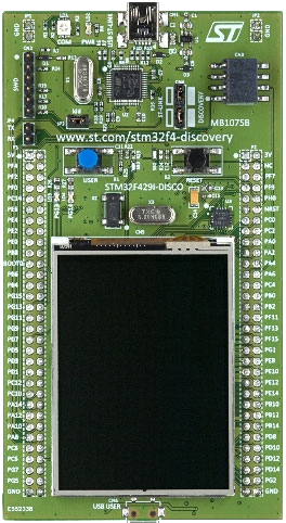
This page discusses issues unique to NuttX configurations for the STMicro STM32F429I-DISCO development board featuring the STM32F429ZIT6 MCU. The STM32F429ZIT6 is a 180MHz Cortex-M4 operation with 2Mbit Flash memory and 256kbytes. The board features:
On-board ST-LINK/V2 for programming and debugging,
On-board 64 Mbits (8 Mbytes) External SDRAM (1 Mbit x 16-bit x 4-bank)
L3GD20, ST MEMS motion sensor, 3-axis digital output gyroscope,
TFT 2.4” LCD, 262K color RGB, 240 x 320 pixels
Touchscreen controller
Two user LEDs and two push-buttons,
USB OTG FS with micro-AB connector, and
Easy access to most MCU pins.
- NOTE: Includes basic NSH command support with full 8MByte SDRAM + the
internal 256K. Unsupported are the LCD and USB interfaces.
The board pin configuration to support on-board SDRAM and LCD prevents use of the OTG FS module which is normally used for USB NSH sessions. Instead, the board routes the OTG HS pins to the USB OTG connector.
The NSH configuration / testing that has been done so far was performed by connecting an external RS-232 line driver to pins PA9 (TX) and PA10 (RX) and configuring USART1 as the NSH console.
Refer to the http://www.st.com website for further information about this board (search keyword: 429i-disco)
NOTE: This port was based on the original discovery kit, STM32F429I-DISCO. That board has been superseded by the new STM32F429I-DISC1.
Setup and Programming Flash
I use a USB cable to power and program it. And I use a USB/Serial connected to pins PA9 and PA10 for the serial console (See the section “UARTs” below).
FLASH may be programmed:
Via USB using STM32 ST-Link Utility
Via USB using OpenOCD. This command may be used to flash the firmware using OpenOCD:
$ sudo openocd -f interface/stlink-v2.cfg -f target/stm32f4x.cfg -c init -c "reset halt" -c "flash write_image erase nuttx.bin 0x08000000"
Via JTAG/SWD connected to the SWD connector CN2.
CN4 Jumpers. Remove jumpers to enable signals at SWD connector CN2.:
SWD 6-Pin STM32F429i-Discovery Connector CN2
Pin   Signal Name       Description
----- ------ ---------- ------------------------------
Pin 1 AIN_1  VDD_TARGET VDD from application
Pin 2 T_JCLK SWCLK      SWD Clock
Pin 3 GND    GND        Ground
Pin 4 T_JTMS SWDIO      SWD data input/output
Pin 5 T_NRST NRST       Reset of target MCU
Pin 6 T_SWO  SWO        Reserved

SWD 20-pin J-Link Connector
Pin    Name      Type   Description
------ --------- ------ ------------------------------
Pin  1 VTref     Input  Target reference voltage
Pin  2 Vsupply   NC     Not connected in J-Link
Pin  3 Not used  NC     Not used in J-Link
Pin  5 Not used  NC     Not used in J-Link
Pin  7 SWDIO     I/O    Bi-directional data pin
Pin  9 SWCLK     Output Clock signal to target CPU
Pin 11 Not used  NC     Not used in J-Link
Pin 13 SWO       Output Serial wire output trace port
Pin 15 RESET     I/O    Target CPU reset signal (nRST)
Pin 17 Not used  NC     Not connected in J-Link
Pin 19 5V-Supply Output Supplies power to some boards.

Pins 4, 45, 8, 10, 12, 14, 16, 18 and 20 are GND pins in J-Link.  They
should also be connected to ground in the target system.
LEDs
The STM32F429I-DISCO board has two user LEDs; green, and red on the board. These LEDs are not used by the board port unless CONFIG_ARCH_LEDS is defined. In that case, the usage by the board port is defined in include/board.h and src/up_leds.c. The LEDs are used to encode OS-related events as follows:
SYMBOL                Meaning                 LED1*    LED2
                                              green    red
-------------------  -----------------------  -------  -------
LED_STARTED          NuttX has been started   ON       OFF
LED_HEAPALLOCATE     Heap has been allocated  OFF      ON
LED_IRQSENABLED      Interrupts enabled       ON       ON
LED_STACKCREATED     Idle stack created       OFF      ON
LED_INIRQ            In an interrupt**        ON       ON
LED_SIGNAL           In a signal handler      N/C      ON
LED_ASSERTION        An assertion failed      ON       ON
LED_PANIC            The system has crashed   ON       BLINK
LED_IDLE             STM32 is is sleep mode   (Optional, not used)

* In normal mode, LED1 will be on and LED2 might flicker a bit as IRQs
  and SIGNALS are processed.
* If LED1 is on and LED2 is blinking, then NuttX probably failed to boot
  or is in a PANIC condition.
UARTs
On the STM32F429I-DISCO board, because of pin mappings to support the onboard SDRAM and LCD, the only UARTs that have both RX and TX pins available are USART1 and UART5. Other USARTS could be used for RX or TX only, or they could be used for full-duplex if the other pin functions aren’t being used (i.e. LCD or SDRAM).
UART/USART PINS
Default Serial Console
USART1 is enabled as the serial console in all configurations (see */defconfig). USART1 RX and TX are configured on pins PA10 and PA9, respectively (see include/board.h).:
Header 32X2 P1
--------------
Pin 1  5V
Pin 51 PA10
Pin 52 PA9
Pin 63 GND
If solder bridges SB11 and SB12 are closed, then USART1 will be connected to the ST-Link and should be available over USB as a virtual COM interface.
Timer Inputs/Outputs
- ::
- TIM1
CH1 PA8[1], PE9[1] CH2 PA9, PE11[1] CH3 PA10, PE13[1] CH4 PA11[1], PE14[1]
- TIM2
CH1 PA0[1], PA15[1], PA5 CH2 PA1[1], PB3[1] CH3 PA2[1], PB10[1] CH4 PA3[1], PB11[1]
- TIM3
CH1 PA6[1], PB4, PC6[1] CH2 PA7[1], PB5[1], PC7[1] CH3 PB0[1], PC8 CH4 PB1[1], PC9[1]
- TIM4
CH1 PB6[1], PD12[1] CH2 PB7, PD13[1] CH3 PB8[1], PD14[1] CH4 PB9[1], PD15[1]
- TIM5
CH1 PA0[1], PH10[1] CH2 PA1[1], PH11[1] CH3 PA2[1], PH12[1] CH4 PA3[1], PI0[2]
- TIM8
CH1 PC6[1], PI5[2] CH2 PC7[1], PI6[2] CH3 PC8, PI7[2] CH4 PC9[1], PI2[2]
- TIM9
CH1 PA2[1], PE5 CH2 PA3[1], PE6
- TIM10
CH1 PB8[1], PF6
- TIM11
CH1 PB9[1], PF7[1]
- TIM12
CH1 PH6[1], PB14[1] CH2 PC15[1], PH9[1]
- TIM13
CH1 PA6[1], PF8[1]
- TIM14
CH1 PA7[1], PF9[1]
[1] Indicates pins that have other on-board functions and should be used only with care (See table 6 in the STM32F429I-DISCO User Guide). The rest are free I/O pins (This need to be updated. They are incorrect!) [2] Port I pins are not supported by the MCU
FMC SDRAM
On-board SDRAM
The STM32F429I-DISCO has 8 MBytes on-board SDRAM connected to the MCU’s SDRAM Bank 2 connections (Bank 6 of the FMC). This means the 8 MiB (when enabled) is mapped to address 0xD0000000-0xD07FFFFF. The port for the STM32F429I-DISCO board includes support for using the onboard 8M SDRAM.
Configuration Options
Internal SRAM is available in all members of the STM32 family. The F4 family also contains internal CCM SRAM. This SRAM is different because it cannot be used for DMA. So if DMA needed, then the following should be defined to exclude CCM SRAM from the heap:
CONFIG_STM32_CCMEXCLUDE : Exclude CCM SRAM from the HEAP
In addition to internal SRAM, SRAM may also be available through the FMC. In order to use FMC SDRAM, the following additional things need to be present in the NuttX configuration file:
CONFIG_STM32_FMC=y          : Enables the FMC and the 8MiB SDRAM
CONFIG_STM32_EXTERNAL_RAM=y : Indicates that RAM is available via the
                              FMC (as opposed to an LCD or FLASH).
CONFIG_HEAP2_BASE           : The base address of the RAM in the FMC
                              address space.  This should be 0xD0000000.
CONFIG_HEAP2_SIZE           : The size of the RAM in the FMC
                              address space.  This should be 8388608.
CONFIG_MM_REGIONS           : Must be set to a large enough value to
                              include the FMC SDRAM (1, 2 or 3 depending
                              if the CCM RAM and/or FMC SDRAM are enabled).
SRAM Configurations
There are 4 possible SRAM configurations:
Configuration 1. System SRAM (only)
                 CONFIG_MM_REGIONS == 1
                 CONFIG_STM32_EXTERNAL_RAM NOT defined
                 CONFIG_STM32_CCMEXCLUDE defined
Configuration 2. System SRAM and CCM SRAM
                 CONFIG_MM_REGIONS == 2
                 CONFIG_STM32_EXTERNAL_RAM NOT defined
                 CONFIG_STM32_CCMEXCLUDE NOT defined
Configuration 3. System SRAM and FMC SDRAM
                 CONFIG_MM_REGIONS == 2
                 CONFIG_STM32_EXTERNAL_RAM defined
                 CONFIG_STM32_CCMEXCLUDE defined
Configuration 4. System SRAM, CCM SRAM, and FMC SDRAM
                 CONFIG_MM_REGIONS == 3
                 CONFIG_STM32_EXTERNAL_RAM defined
                 CONFIG_STM32_CCMEXCLUDE NOT defined
Configurations
Each STM32F429I-DISCO configuration is maintained in a sub-directory and can be selected as follow:
tools/configure.sh stm32f429i-disco:<subdir>
Where <subdir> is one of the following:
bootlogo
This board configuration enables the framebuffer test (like the ‘fb’ profile) and includes the NuttX NX Logo as boot splash screen.
Note: the Logo seems upside down. It should be nice to have a rotation option for the boot logo splash image.
extflash
This is another NSH example. If differs from other ‘nsh’ configurations in that this configuration defines an external 8 MByte SPI FLASH (the SST25VF064C part from Silicon Storage Technology, Inc.) which must be be connected to the Discovery board’s SPI4 pins on the expansion pins. Additionally, this demo uses UART1 for the console
NOTES:
This configuration assumes an SST25VF064C 8Mbyte SPI FLASH is connected to SPI4 on the following Discovery board Pins:
SCK:   Port PE2   Board Connector P1, Pin 15
MOSI:  Port PE6   Board Connector P1, Pin 11
MISO:  Port PE5   Board Connector P1, Pin 14
CS:    Port PE4   Board Connector P1, Pin 13
This configuration does have UART1 output enabled and set up as the system logging device. To use this UART, you must add an external RS-232 line driver to the UART1 pins of the DISCO board on PA9 and PA10 of connector P1.
fb
STM32F429I-DISCO LTDC Framebuffer demo example. This is a simple configuration used for some basic (non-graphic) debug of the framebuffer character drivers using apps/examples/fb. It simply opens the framebuffer device and draws concentric rectangles of different colors in the framebuffer:
nsh> fb
Also included is the touchscreen test of apps/examples/touchscreen. This example will simply open the touchscreen driver then collect and display touch inputs:
nsh> tc 1
tc_main: nsamples: 1
tc_main: Initializing external touchscreen device
tc_main: Opening /dev/input0
Sample     :
   npoints : 1
Point 1    :
        id : 0
     flags : 3c
         x : 2296
         y : 2311
         h : 0
         w : 0
  pressure : 1
Terminating!
nsh>
lgvl
STM32F429I-DISCO LittlevGL demo example.
The ltdc is initialized during boot up. Interaction with NSH is via the serial console at 115200 8N1 baud. From the nsh command line execute the lvgldemo example:
nsh> lvgldemo
The test will execute the calibration process and then run the LittlevGL demo project.
nsh
Configures the NuttShell (nsh) located at apps/examples/nsh. The Configuration enables the serial interfaces on UART2. Support for builtin applications is enabled, but in the base configuration no builtin applications are selected (see NOTES below).
NOTES:
This configuration uses the mconf-based configuration tool. To change this configuration using that tool, you should:
Build and install the kconfig-mconf tool. See nuttx/README.txt see additional README.txt files in the NuttX tools repository.
Execute ‘make menuconfig’ in nuttx/ in order to start the reconfiguration process.
By default, this configuration uses the ARM EABI toolchain for Windows and builds under Cygwin (or probably MSYS). That can easily be reconfigured, of course.:
CONFIG_HOST_WINDOWS=y                   : Builds under Windows
CONFIG_WINDOWS_CYGWIN=y                 : Using Cygwin
CONFIG_ARM_TOOLCHAIN_GNU_EABI=y      : GNU EABI toolchain for Windows
This example supports the PWM test (apps/examples/pwm) but this must be manually enabled by selecting:
CONFIG_PWM=y              : Enable the generic PWM infrastructure
CONFIG_STM32_TIM4=y       : Enable TIM4
CONFIG_STM32_TIM4_PWM=y   : Use TIM4 to generate PWM output
See also apps/examples/README.txt
Special PWM-only debug options:
CONFIG_DEBUG_PWM_INFO
This example supports the Quadrature Encode test (apps/examples/qencoder) but this must be manually enabled by selecting:
CONFIG_EXAMPLES_QENCODER=y : Enable the apps/examples/qencoder
CONFIG_SENSORS=y           : Enable support for sensors
CONFIG_SENSORS_QENCODER=y          : Enable the generic Quadrature Encoder infrastructure
CONFIG_STM32_TIM8=y        : Enable TIM8
CONFIG_STM32_TIM2=n        : (Or optionally TIM2)
CONFIG_STM32_TIM8_QE=y     : Use TIM8 as the quadrature encoder
CONFIG_STM32_TIM2_QE=y     : (Or optionally TIM2)
See also apps/examples/README.txt. Special debug options:
CONFIG_DEBUG_SENSORS
This example supports the watchdog timer test (apps/examples/watchdog) but this must be manually enabled by selecting:
CONFIG_EXAMPLES_WATCHDOG=y : Enable the apps/examples/watchdog
CONFIG_WATCHDOG=y          : Enables watchdog timer driver support
CONFIG_STM32_WWDG=y        : Enables the WWDG timer facility, OR
CONFIG_STM32_IWDG=y        : Enables the IWDG timer facility (but not both)
The WWDG watchdog is driven off the (fast) 42MHz PCLK1 and, as result, has a maximum timeout value of 49 milliseconds. for WWDG watchdog, you should also add the following to the configuration file:
CONFIG_EXAMPLES_WATCHDOG_PINGDELAY=20
CONFIG_EXAMPLES_WATCHDOG_TIMEOUT=49
The IWDG timer has a range of about 35 seconds and should not be an issue.
USB Support (CDC/ACM device):
CONFIG_STM32_OTGFS=y          : STM32 OTG FS support
CONFIG_USBDEV=y               : USB device support must be enabled
CONFIG_CDCACM=y               : The CDC/ACM driver must be built
CONFIG_NSH_BUILTIN_APPS=y     : NSH built-in application support must be enabled
Using the USB console.
The STM32F429I-DISCO NSH configuration can be set up to use a USB CDC/ACM (or PL2303) USB console. The normal way that you would configure the the USB console would be to change the .config file like this:
CONFIG_STM32_OTGFS=y           : STM32 OTG FS support
CONFIG_USART2_SERIAL_CONSOLE=n : Disable the USART2 console
CONFIG_DEV_CONSOLE=n           : Inhibit use of /dev/console by other logic
CONFIG_USBDEV=y                : USB device support must be enabled
CONFIG_CDCACM=y                : The CDC/ACM driver must be built
CONFIG_CDCACM_CONSOLE=y        : Enable the CDC/ACM USB console.
NOTE: When you first start the USB console, you have hit ENTER a few times before NSH starts. The logic does this to prevent sending USB data before there is anything on the host side listening for USB serial input.
Here is an alternative USB console configuration. The following configuration will also create a NSH USB console but this version will use /dev/console. Instead, it will use the normal /dev/ttyACM0 USB serial device for the console:
CONFIG_STM32_OTGFS=y           : STM32 OTG FS support
CONFIG_USART2_SERIAL_CONSOLE=y : Keep the USART2 console
CONFIG_DEV_CONSOLE=y           : /dev/console exists (but NSH won't use it)
CONFIG_USBDEV=y                : USB device support must be enabled
CONFIG_CDCACM=y                : The CDC/ACM driver must be built
CONFIG_CDCACM_CONSOLE=n        : Don't use the CDC/ACM USB console.
CONFIG_NSH_USBCONSOLE=y        : Instead use some other USB device for the console
The particular USB device that is used is:
CONFIG_NSH_USBCONDEV="/dev/ttyACM0"
The advantage of this configuration is only that it is easier to bet working. This alternative does has some side effects:
When any other device other than /dev/console is used for a user interface, linefeeds (n) will not be expanded to carriage return / linefeeds (rn). You will need to set your terminal program to account for this.
/dev/console still exists and still refers to the serial port. So you can still use certain kinds of debug output (see include/nuttx/debug.h, all debug output from interrupt handlers will be lost.
But don’t enable USB debug output! Since USB is console is used for USB debug output and you are using a USB console, there will be infinite loops and deadlocks: Debug output generates USB debug output which generatates USB debug output, etc. If you want USB debug output, you should consider enabling USB trace (CONFIG_USBDEV_TRACE) and perhaps the USB monitor (CONFIG_USBMONITOR).
See the usbnsh configuration below for more information on configuring USB trace output and the USB monitor.
USB OTG FS Host Support. The following changes will enable support for a USB host on the STM32F429I-DISCO, including support for a mass storage class driver:
Device Drivers -> CONFIG_USBDEV=n : Make sure the USB device support is disabled CONFIG_USBHOST=y : Enable USB host support CONFIG_USBHOST_ISOC_DISABLE=y
Device Drivers -> USB Host Driver Support CONFIG_USBHOST_MSC=y : Enable the mass storage class
System Type -> STM32 Peripheral Support CONFIG_STM32_OTGHS=y : Enable the STM32 USB OTG FH block (FS mode) CONFIG_STM32_SYSCFG=y : Needed for all USB OTF HS support
RTOS Features -> Work Queue Support CONFIG_SCHED_WORKQUEUE=y : High priority worker thread support is required CONFIG_SCHED_HPWORK=y : for the mass storage class driver.
File Systems -> CONFIG_FS_FAT=y : Needed by the USB host mass storage class.
Board Selection -> CONFIG_BOARDCTL=y
With those changes, you can use NSH with a FLASH pen driver as shown belong. Here NSH is started with nothing in the USB host slot:
NuttShell (NSH) NuttX-x.yy nsh> ls /dev /dev: console null ttyS0
After inserting the FLASH drive, the /dev/sda appears and can be mounted like this:
nsh> ls /dev /dev: console null sda ttyS0 nsh> mount -t vfat /dev/sda /mnt/stuff nsh> ls /mnt/stuff /mnt/stuff: -rw-rw-rw- 16236 filea.c
And files on the FLASH can be manipulated to standard interfaces:
nsh> echo “This is a test” >/mnt/stuff/atest.txt nsh> ls /mnt/stuff /mnt/stuff: -rw-rw-rw- 16236 filea.c -rw-rw-rw- 16 atest.txt nsh> cat /mnt/stuff/atest.txt This is a test nsh> cp /mnt/stuff/filea.c fileb.c nsh> ls /mnt/stuff /mnt/stuff: -rw-rw-rw- 16236 filea.c -rw-rw-rw- 16 atest.txt -rw-rw-rw- 16236 fileb.c
To prevent data loss, don’t forget to un-mount the FLASH drive before removing it:
nsh> umount /mnt/stuff
I used this configuration to test the USB hub class. I did this testing with the following changes to the configuration (in addition to those listed above for base USB host/mass storage class support):
Drivers -> USB Host Driver Support CONFIG_USBHOST_HUB=y : Enable the hub class CONFIG_USBHOST_ASYNCH=y : Asynchronous I/O supported needed for hubs
Board Selection -> CONFIG_STM32F429IDISCO_USBHOST_STACKSIZE=2048 (bigger than it needs to be)
RTOS Features -> Work Queue Support CONFIG_SCHED_LPWORK=y : Low priority queue support is needed CONFIG_SCHED_LPNTHREADS=1 CONFIG_SCHED_LPWORKSTACKSIZE=1024
NOTES:
It is necessary to perform work on the low-priority work queue (vs. the high priority work queue) because deferred hub-related work requires some delays and waiting that is not appropriate on the high priority work queue.
Stack usage make increase when USB hub support is enabled because the nesting depth of certain USB host class logic can increase.
STATUS: 2015-04-30 Appears to be fully functional.
nx
This a simple test using the graphic example at apps/example/nx. This configuration illustrates the use of the LCD with the lower performance SPI interface.
nxwm
This is a special configuration setup for the NxWM window manager UnitTest.
NOTES:
The NxWM window manager can be found here:
apps/graphics/NxWidgets/nxwm
The NxWM unit test can be found at:
apps/graphics/NxWidgets/UnitTests/nxwm
STATUS: 17-01-08: There are instabilities in this configuration that make it not usable on this platform. While the equivalent configuration works on other platforms, this one does not: The calculator display does not form properly. There are fails in the NxTerm display, usually around the point where the display should scroll up.
Update: With all optimizations disabled, the issue seems to go away. So this is most likely due to using high levels of optimization with a bleeding edge GCC toolchain.
17-11-15: The original configuration used the slower SPI LCD interface. The configuration was converted to use the high performance LTDC frame buffer interface. Performance is now excellent and I see none of the instabilities mentioned above even at high levels of optimization.
The difficulty that I experienced was touching the tiny icons on the menus. The touscreen controller (along with my fat fingers) does not appear to have sufficient precision to work in this way. Larger icons would likely make the interface easier to use.
usbnsh
This is another NSH example. If differs from other ‘nsh’ configurations in that this configurations uses a USB serial device for console I/O. Such a configuration is useful on the stm32f429i-disco which has no builtin RS-232 drivers.
NOTES:
This configuration uses the mconf-based configuration tool. To change this configuration using that tool, you should:
Build and install the kconfig-mconf tool. See nuttx/README.txt see additional README.txt files in the NuttX tools repository.
Execute ‘make menuconfig’ in nuttx/ in order to start the reconfiguration process.
This configuration does have UART1 output enabled and set up as the system logging device. To use this UART, you must add an external RS-232 line driver to the UART1 pins of the DISCO board on PA9 and PA10 of connector P1.
usbmsc
This is an example of enabling the FS OTG port on the DISCO board for mass storage use. It provides an NSH session on UART1 to allow accessing the connected USB mass storage device. Such a configuration is useful on the stm32f429i-disco which has no onboard SD card or mass storage solution.
NOTES:
This configuration uses UART1 as the system console. To use this UART, you must add an external RS-232 line driver to the UART1 pins of the DISCO board on PA9 and PA10 of connector P1.
The mass storage device will appear as /dev/sda and supports FAT formatted “thumb” flash drives with:
nsh> mount -t vfat /dev/sda /mount_name
STM32F429I-DISCO LTDC Framebuffer demo example
STM32F429I-DISCO LTDC Framebuffer demo example
Configure and build
- ::
cd tools ./configure -a <appdir> stm32f429i-disco/fb cd .. make
Framebuffer calculation
Use the helper script boards/stm32f429i-disco/tools/fbcalc.sh for calculating the heap2 and framebuffer memory region. The script assumes that all overlay buffers (LTDC and DMA2D) located in heap2 memory region starting at address 0xD0000000. When changing the display size (when using a custom display), DMA2D overlay size or the pixel format you have to recalculate the heap2 settings. In this configuration all overlays (LTDC and DMA2D) positioned at the end of heap2.
Configuration
This configuration provides 2 LTDC (visible overlays) and 2 DMA2D overlays with pixel format RGB565 and a resolution of 240x320.
Loading
st-flash write nuttx.bin 0x8000000
Executing
The ltdc is initialized during boot up. Interaction with NSH is via the serial console at 115200 8N1 baud. From the nsh commandline execute the fb example:
nsh> fb
The test will put a pattern of concentric squares in the framebuffer and terminate.
You can also test overlay hardware acceleration functionality by executing the following command (shows a commandline help):
nsh> fboverlay