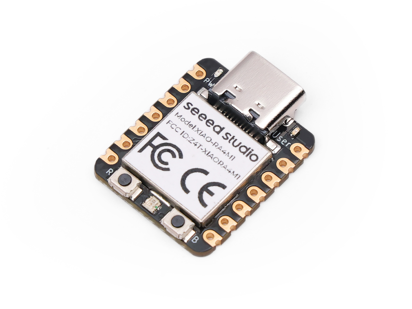
Seeed Studio XIAO RA4M1
The Seeed Studio XIAO RA4M1 is a general purpose board supplied by Seeed Studio and it is compatible with the Renesas RA4M1 ecosystem, sharing the same MCU as Arduino R4 Minima (R7FA4M1AB3CFM).
Features
Renesas RA4M1, ARM® Dual Cortex-M4 @ 48MHz
32kB SRAM, 256KkB Flash, 8KB EEPROM
Security: AES128/256
USB Type-C interface
19 Pins:14x Analog,19x Digital, 2x IIC, 2x UART, 2x SPI
1 user LED, 1 power LED,1 RGB LED (WS2812)
1 RESET button, 1 BOOT button
Serial Console
By default, a serial console appears on pins 6 (TX GPIO) and pin 7 (RX GPIO). This console runs a 115200-8N1.
User LED
The USER LED, the yellow LED on the XIAO RA4M1, is connected to P011 according to the schematic diagram.
Pin Mapping
Pads numbered anticlockwise from USB connector.
Pad |
Signal |
Notes |
|---|---|---|
0 |
P014 |
D0/A0 |
1 |
P000 |
D1/A1 |
2 |
P001 |
D2/A2 |
3 |
P002 |
D3/A3 |
4 |
P006 |
D4/SDA |
5 |
P100 |
D5/SCL |
6 |
P301 |
D6/Default TX for UART0 serial console |
7 |
P301 |
D7/Default RX for UART0 serial console |
8 |
P111 |
D8/SCK |
9 |
P110 |
D9/MISO |
10 |
P109 |
D10/MOSI |
11 |
3V3 |
Power output to peripherals |
12 |
Ground |
|
13 |
VIN |
+5V Supply to board |
Power Supply
The working voltage of the MCU is 3.3V. Voltage input connected to general I/O pins may cause chip damage if it’s higher than 3.3V.
Installation
Configure and build NuttX:
$ git clone https://github.com/apache/nuttx.git nuttx
$ git clone https://github.com/apache/nuttx-apps.git apps
$ cd nuttx
$ make distclean
$ ./tools/configure.sh xiao-ra4m1:nsh
$ make V=1
2. Connect the Seeed Studio XIAO RA4M1, and enter “Renesas RA USB Boot” mode,
then, flash the nuttx.hex file using rfp-cli:
(https://www.renesas.com/en/software-tool/renesas-flash-programmer-programming-gui)
Example command:
rfp-cli -device ra -port /dev/ttyACM0 -p ./build/nuttx.hex
To access the console, TX and RX pins must be connected to the device such as USB-serial converter.
Configurations
nsh
Basic NuttShell configuration (console enabled in UART0, at 115200 bps).
combo
This configuration enabled NuttShell via Serial and enabled led and gpio examples:
Testing leds:
$nsh> leds
leds_main: Starting the led_daemon
leds_main: led_daemon started

led_daemon (pid# 5): Running
led_daemon: Opening /dev/userleds
led_daemon: Supported LEDs 0x01
led_daemon: LED set 0x01
$nsh> led_daemon: LED set 0x00
led_daemon: LED set 0x01
led_daemon: LED set 0x00
led_daemon: LED set 0x01
led_daemon: LED set 0x00
led_daemon: LED set 0x01
Testing gpios:
PIN/GPIO |
Mode |
Device |
|---|---|---|
D0/P014 |
Input |
/dev/gpio0 |
D1/P000 |
Output |
/dev/gpio1 |
$nsh> gpio /dev/gpio0
Driver: /dev/gpio0
  Input pin:     Value=0
$nsh> gpio /dev/gpio0
Driver: /dev/gpio0
  Input pin:     Value=1