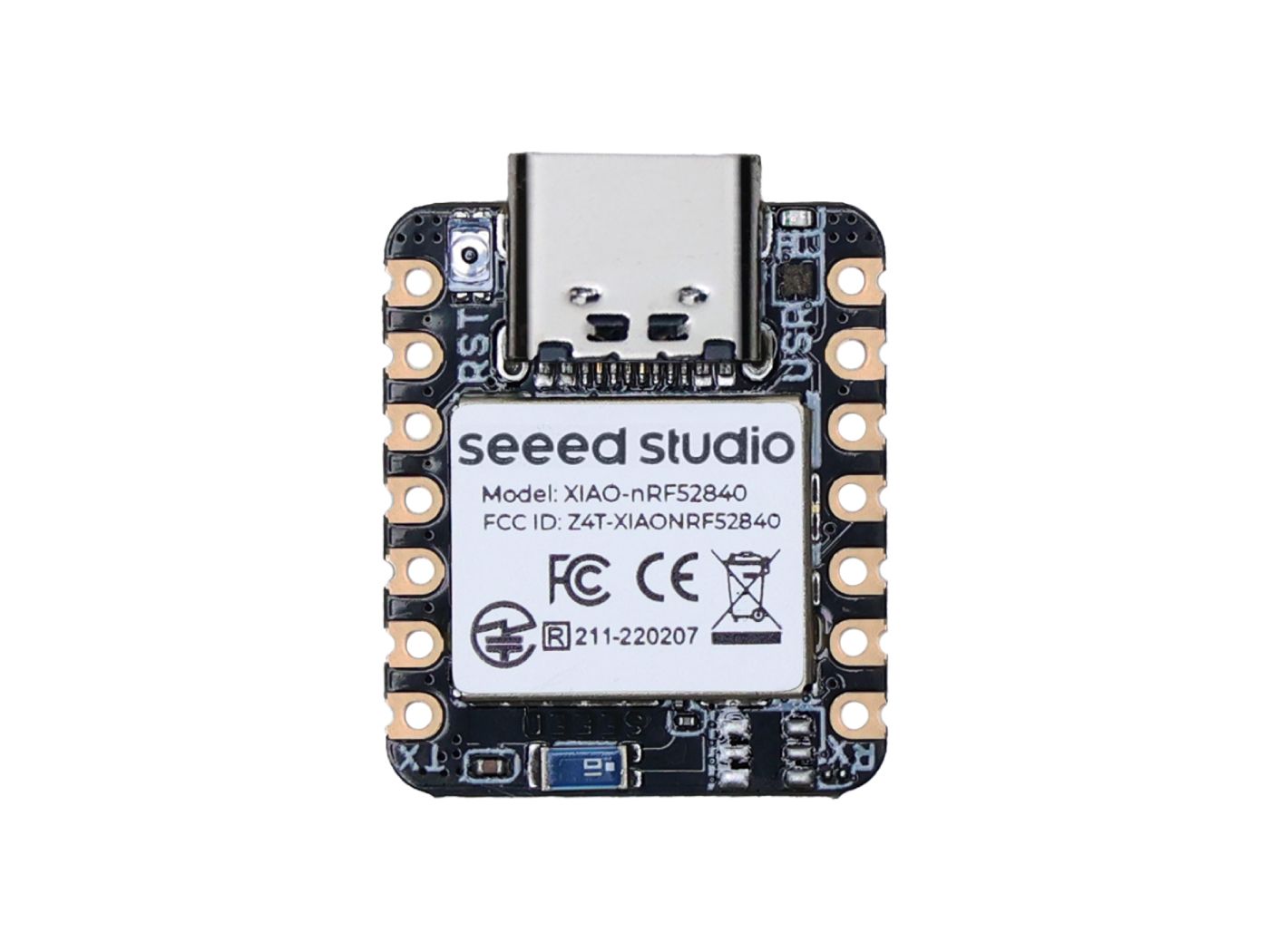
Seeed Studio XIAO nRF52840
The Seeed Studio XIAO nRF52840 is a general purpose board supplied by Seeed Studio and it is compatible with the Nordic nRF52840 ecosystem as they share the same MCU.
Features
Nordic nRF52840, ARM® Cortex®-M4 32-bit processor with FPU, 64 MHz
256 KB RAM,1MB Flash 2MB onboard Flash
Bluetooth 5.0/BLE/NFC
1xUART, 1xI2C, 1xSPI, 1xNFC, 1xSWD, 11xGPIO(PWM)
USB Type-C interface
1 RGB LED, 1 charge LED
1 RESET button
Serial Console
By default, a serial console appears on pins 6 (TX P1.11) and pin 7 (RX P1.12). This console runs a 115200-8N1. The board can be configured to use the USB connection as the serial console.
User LED
The RGB LED is connected as follows:
Color |
Pin |
|---|---|
RED |
P0.26 |
GREEN |
P0.30 |
BLUE |
P0.6 |
Pin Mapping
Pads numbered anticlockwise from USB connector.
Pad |
Signal |
Notes |
|---|---|---|
0 |
P0.02 |
D0/A0 |
1 |
P0.03 |
D1/A1 |
2 |
P0.28 |
D2/A2 |
3 |
P0.29 |
D3/A3 |
4 |
P0.04 |
D4/SDA |
5 |
P0.05 |
D5/SCL |
6 |
P1.11 |
Default TX for UART0 serial console |
7 |
P1.12 |
Default RX for UART0 serial console |
8 |
P1.13 |
D8/SCK |
9 |
P1.14 |
D9/MISO |
10 |
P1.15 |
D10/MOSI |
11 |
3V3 |
Power output to peripherals |
12 |
Ground |
|
13 |
VIN |
+5V Supply to board |
Power Supply
The working voltage of the MCU is 3.3V. Voltage input connected to general I/O pins may cause chip damage if it’s higher than 3.3V.
Installation
Download UF2 Tools:
$ git clone https://github.com/microsoft/uf2.git
Configure and build NuttX:
$ git clone https://github.com/apache/nuttx.git nuttx
$ git clone https://github.com/apache/nuttx-apps.git apps
$ cd nuttx
$ make distclean
$ ./tools/configure.sh xiao-nrf52840:nsh
$ make V=1
Convert nuttx.hex to UF2 format using U2F Tools:
$ python3 uf2/utils/uf2conv.py -c -f 0xADA52840 -i nuttx.hex -o nuttx.uf2
4. Connect the Seeed Studio XIAO nRF52840, and enter bootloader mode by rapidly clicking it twice. The board will be detected as a USB Mass Storage Device. Then copy “nuttx.uf2” into the device.
To access the console, TX and RX pins must be connected to the device such as USB-serial converter.
Configurations
nsh
Basic NuttShell configuration (console enabled in UART0, at 115200 bps).
usbnsh
Basic NuttShell configuration using CDC/ACM serial (console enabled in USB Port, at 115200 bps).
jumbo
This configuration enabled NuttShell via USB and enabled leds and gpio examples:
Testing leds:
$nsh> leds
leds_main: Starting the led_daemon
leds_main: led_daemon started

led_daemon (pid# 3): Running
led_daemon: Opening /dev/userleds
led_daemon: Supported LEDs 0x07
led_daemon: LED set 0x01
$nsh> led_daemon: LED set 0x02
led_daemon: LED set 0x03
led_daemon: LED set 0x04
led_daemon: LED set 0x05
led_daemon: LED set 0x06
led_daemon: LED set 0x07
Testing gpios:
PIN/GPIO |
Mode |
Device |
|---|---|---|
D0/P0.02 |
Input |
/dev/gpio0 |
D2/P0.28 |
Output |
/dev/gpio1 |
D1/P0.03 |
Input |
/dev/gpio2 |
$nsh> gpio /dev/gpio0
Driver: /dev/gpio0
  Input pin:     Value=0
$nsh> gpio /dev/gpio0
Driver: /dev/gpio0
  Input pin:     Value=1

$nsh> gpio -o 0 /dev/gpio1
Driver: /dev/gpio1
  Output pin:    Value=1
  Writing:       Value=0
  Verify:        Value=0

$nsh> gpio -w 1 /dev/gpio2
Driver: /dev/gpio2
  Interrupt pin: Value=0
  Verify:        Value=1