i.MX RT1060 EVK
i.MX RT1060 EVK is an evaluation kit by NXP company. This kit uses the i.MX RT1060 crossover MCU with ARM Cortex M7 core.
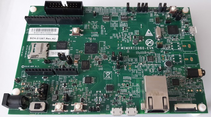
i.MX RT1060 EVK
Features
- Processor
MIMXRT1062DVL6A processor
- Memory
1 Mb OCRAM memory
256 Mb SDRAM memory
512 Mb Hyper Flash - Populated but 0 ohm DNP
64 Mb QSPI Flash
TF socket for SD card
- Display and Audio
Parallel LCD connector
Camera connector
Audio CODEC
4-pole audio headphone jack
External speaker connection
Microphone
SPDIF connector
- Connectivity
Micro USB host and OTG connectors
Ethernet (10/100T) connector
CAN transceivers (including one CAN FD)
Arduino® interface
- Sensors
FXOS8700CQ 6-Axis Ecompass (3-Axis Mag, 3-Axis Accel)
Serial Console
Virtual console port provided by OpenSDA:
UART1_TXD |
GPIO_AD_B0_12 |
LPUART1_TX |
UART1_RXD |
GPIO_AD_B0_13 |
LPUART1_RX |
Arduino RS-232 Shield:
J22 |
D0 |
UART_RX |
GPIO_AD_B1_07 |
LPUART3_RX |
J22 |
D1 |
UART_TX |
GPIO_AD_B1_06 |
LPUART3_TX |
J-Link External Debug Probe
Install the J-Link Debug Host Tools and make sure they are in your search path.
Attach a J-Link 20-pin connector to J21. Check that jumpers J47 and J48 are off (they are on by default when boards ship from the factory) to ensure SWD signals are disconnected from the OpenSDA microcontroller.
Configurations
can
This is an nsh configuration (see below) with added support of CAN driver. FlexCAN3 is chosen as default, the change can be made at System type peripheral selection. Please note that only FlexCAN3 and FlexCAN2 is available on this board.
Bitrate and sample point can be also changed at System type peripheral selection, basic values are 1 MHz for bitrate and 0.80 for sample point. The FlexCAN driver for imxrt runs at 80 MHz clock frequency.
The configuration also includes CAN utilities as candump and cansend.
canfd
This is an nsh configuration (see below) with added support of CAN_FD driver. FlexCAN3 is chosen as default, please note that only FlexCAN3 is capable of providing CAN_FD support.
Bitrate and sample point can be also changed at System type peripheral selection, basic values are 1 MHz for bitrate and 0.80 for sample point for arbitration phase and 4 MHz (bitrate) and 0.90 (sample point) for data phase. The FlexCAN driver for imxrt runs at 80 MHz clock frequency.
The configuration also includes CAN utilities as candump and cansend.
knsh
This is identical to the nsh configuration below except that NuttX is built as a protected mode, monolithic module and the user applications are built separately. For further information about compiling and running this configuration please refer to imxrt1064-evk documentation.
netnsh
This configuration is similar to the nsh configuration except that is has networking enabled, both IPv4 and IPv6. This NSH configuration is focused on network-related testing.
nsh
Configures the NuttShell (nsh) located at examples/nsh. This NSH configuration is focused on low level, command-line driver testing. Built-in applications are supported, but none are enabled. This configuration does not support a network.
lvgl
Configures the Littlev graphic library (lvgl) demo located under examples/lvgldemo. This configuration needs the optional LCD model RK043FN02H-CT from NXP. The LCD panel comes with the integrated capacitive touchscreen sensor FT5336GQQ connected to the LPI2C1 bus, address 0x38. NuttX support such touchscreen device via the driver ft5x06 (drivers/input/ft5x06.c). At the moment only the polling method is available, the board features an interrupt line connected to the touchscreen sensor IC.
IMXRT1060 MCU provides the integrated LCD driver.
- The LCD panel features:
size 4.3”
resolution 480×272 RGB
backlight driver
dimensions [mm]: 105.5 (W) x 67.2(H) x 4.35(D) Max.
To run the lvgl demo please type “lvgldemo” at nsh prompt:
nsh> lvgldemo