Adafruit QT Py RP2040

The QT Py RP2040 is a tiny general purpose RP2040 board supplied by Adafruit.

../../../../../_images/QT-Py.png

Features

  • RP2040 microcontroller chip

  • Dual-core ARM Cortex M0+ processor, flexible clock running up to 133 MHz

  • 264kB of SRAM, and 8MB of on-board Flash memory

  • Castellated module allows soldering direct to carrier boards

  • USB Host and Device support via type C connector.

  • Low-power sleep and dormant modes

  • Drag & drop programming using mass storage over USB

  • 13 multi-function GPIO pins (11 breakout pads and two QT pads)

  • 2× SPI, 2× I2C, 2× UART, 4× 12-bit ADC, 16× controllable PWM channels

  • Accurate clock and timer on-chip

  • Temperature sensor

  • Accelerated floating point libraries on-chip

  • 8 × Programmable IO (PIO) state machines for custom peripheral support
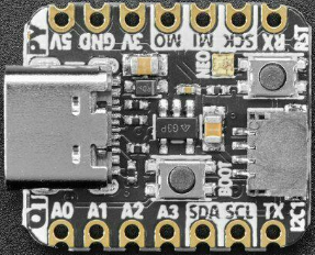
Serial Console

By default a serial console appears on GPIO pins 20 (RX GPIO1) and pin 5 (TX GPIO1). This console runs a 115200-8N1.

The board can be configured to use the USB connection as the serial console.

Buttons and LEDs

A ws2812 (NeoPixel) smart RGB LED controlled by GPIO12 (data) and GPIO11 (power).

There is a BOOT button which if held down when power is first applied or the RESET button is pressed will cause the RP2040 to boot into program mode and appear as a storage device to a USB connecter. Saving a .UF2 file to this device will replace the Flash ROM contents on the RP2040.

A RESET button that allows rebooting the board without disconnecting the power.

Pin Mapping

Pads numbered anticlockwise from USB connector.

Pad

Signal

Notes

1

GPIO26

ADC0

2

GPIO27

ADC1

3

GPIO28

ADC2

4

GPIO29

ADC3

5

GPIO24

6

GPIO25

7

GPIO20

Default TX for UART1 serial console

8

GPIO5

Default RX for UART1 serial console

9

GPIO6

10

GPIO4

11

GPIO3

12

3.3V

Power out to peripherals.

13

Ground

14

5V

The board has a STEMMA QT connector that is also connected to pins GPIO22 (I2C1 SDA) and GPIO23 (I2C1 SCL).

Power Supply

The Raspberry Pi Pico can be powered via the USB connector, or by supplying +5V to pin 14. The board had a diode that prevents power from pin 14 from flowing back to the USB socket, although this can be disabled by connecting on-board solder pads if there is need to run as a usb host.

The Raspberry Pi Pico chip run on 3.3 volts which is supplied by an on board regulator.

Configurations

gpio

NuttShell configuration (console enabled in UART1, at 115200 bps) with GPIO examples.

nsh

Basic NuttShell configuration (console enabled in UART1, at 115200 bps).

nsh-flash

Basic NuttShell configuration (console enabled in UART0, at 115200 bps with SMART flash filesystem.

nshsram

NuttShell configuration (console enabled in UART1, at 115200 bps) with interrupt vectors in RAM.

smp

Basic NuttShell configuration (console enabled in UART1, at 115200 bps) with both ARM cores enabled.

usbnsh

Basic NuttShell configuration (console enabled in USB Port, at 115200 bps).

README.txt

README
======

This directory contains the port of NuttX to the Adafruit QT Py RP2040.
See https://learn.adafruit.com/adafruit-qt-py-2040 for information
about Adafruit QT Py RP2040.

NuttX supports the following RP2040 capabilities:
  - UART  (console port)
    - GPIO 5 (UART1 RX) and GPIO 20 (UART1 TX) are used for the console.
  - I2C
  - SPI (master only)
  - DMAC
  - PWM
  - ADC
  - Watchdog
  - USB device
    - MSC, CDC/ACM serial and these composite device are supported.
    - CDC/ACM serial device can be used for the console.
  - PIO (RP2040 Programmable I/O)
  - Flash ROM Boot
  - SRAM Boot
    - If Pico SDK is available, nuttx.uf2 file which can be used in
      BOOTSEL mode will be created.
  - Persistent flash filesystem in unused flash ROM

NuttX also provide support for these external devices:

  - WS2812 smart pixel support

There is currently no direct user mode access to these RP2040 hardware features:
  - SPI Slave Mode
  - SSI
  - RTC
  - Timers

Installation
============

1. Download Raspberry Pi Pico SDK

  $ git clone -b 1.1.2 https://github.com/raspberrypi/pico-sdk.git

2. Set PICO_SDK_PATH environment variable

  $ export PICO_SDK_PATH=<absolute_path_to_pico-sdk_directory>

3. Configure and build NuttX

  $ git clone https://github.com/apache/nuttx.git nuttx
  $ git clone https://github.com/apache/nuttx-apps.git apps
  $ cd nuttx
  $ make distclean
  $ ./tools/configure.sh raspberrypi-pico:nsh
  $ make V=1

4. Connect Adafruit KB2040 board to USB port while pressing BOOTSEL.
   The board will be detected as USB Mass Storage Device.
   Then copy "nuttx.uf2" into the device.
   (Same manner as the standard Pico SDK applications installation.)

5. To access the console, GPIO 20 (TX) and 5 (RX) pins must be connected to a
   device such as USB-serial converter.

   `usbnsh` configuration provides the console access by USB CDC/ACM serial
   devcice.  The console is available by using a terminal software on the USB
   host.

Defconfigs
==========

- nsh
    Minimum configuration with NuttShell

- nsh-flash
    NuttX shell with SMART flash filesystem.

- nshsram
    Load NuttX binary to SRAM

- smp
    Enable SMP mode. Both Core 0 and Core 1 are used by NuttX.

- usbnsh
    USB CDC/ACM serial console with NuttShell

- composite
    USB composite device (MSC + CDC/ACM) support
    `conn` command enables the composite device.

License exceptions
==================

The following files are originated from the files in Pico SDK.
So, the files are licensed under 3-Clause BSD same as Pico SDK.

- arch/arm/src/rp2040/rp2040_clock.c
- arch/arm/src/rp2040/rp2040_pll.c
- arch/arm/src/rp2040/rp2040_xosc.c
  - These are created by referring the Pico SDK clock initialization.

- arch/arm/src/rp2040/rp2040_pio.c
- arch/arm/src/rp2040/rp2040_pio.h
- arch/arm/src/rp2040/rp2040_pio_instructions.h
  - These provide the similar APIs to Pico SDK's hardware_pio APIs.

- arch/arm/src/rp2040/hardware/*.h
  - These are generated from rp2040.svd originally provided in Pico SDK.