linum-stm32h753bi
This page discusses issues unique to NuttX configurations for the LINUM-STM32H753BI board.
Board information
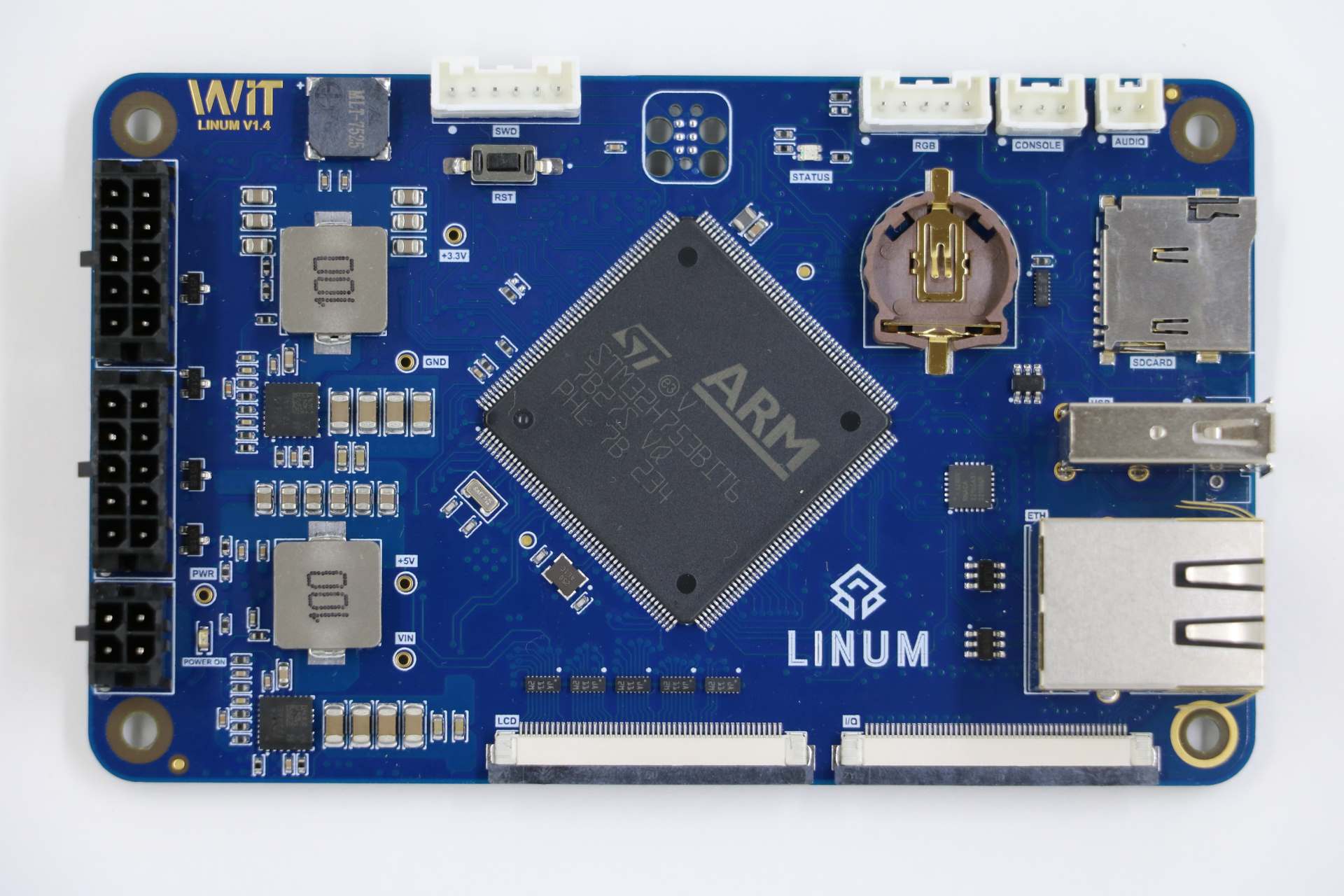
This board was release by Witte Tenology in 2023 and developed based on STM32H753BI microcontroller. The board has 2 expansion connectors used by the LCD display with touchscreen and another for access to other peripherals of microcontroller.
- The board features:
8 to 52V power supply
SWD Pins for use as STLink (Pin header) and TC2030-IDC 6-Pin Tag-Connect Plug-of-Nails™ Connector
Crystal for HS 25MHz
Crystal for RTC 32.768KHz
1 UART serial for debug
1 Led RGB
1 Buzzer without internal oscillator
1 Mono audio up to 3W
1 Ethernet 10/100
1 MicroSD connector supporting 1 or 4-bit bus
1 USB 2.0 Host/Device
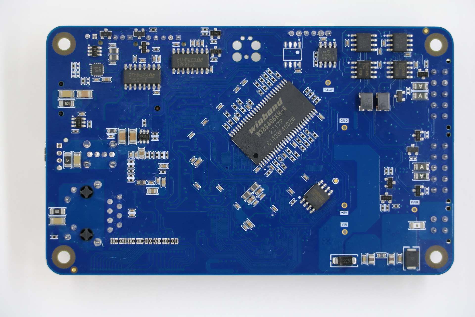
1 EEPROM memory with 512K bits
1 External SRAM memory with 8MB
1 NOR memory with 16MB
2 On-board RS232 Transceiver with RTS/CTS
2 On-board RS485 Transceiver
2 On-board CAN-FD Transceiver
- Expansion connector 1 features:
1 Display RBG 888
1 Capacitive Touchscreen sensor
- Expansion connector 2 features.
1 SPI
1 I2C
1 One Wire
2 DACs
6 PWM Channels
10 ADCs
LEDs
The LINUM-STM32H753BI has 3 software controllable LEDs.
LED RGB
PINS
LED_R
PG2
LED_G
PG3
LED_B
PB2
UART/USART
The LINUM-STM32H753BI used the USART1 for serial debug messages.
USART1
USART1
PINS
TX
PB14
RX
PB15
The LINUM-STM32H753BI board has two on-board RS-232 transceiver connected to USART2 and USART3.
USART2
PINS
TXD
PD5
RXD
PD6
CTS
PD3
RTS
PD4
USART3
PINS
TXD
PB10
RXD
PB11
CTS
PD11
RTS
PD12
The LINUM-STM32H753BI board has two on-board RS-485 transceiver connected to USART4 and USART6.
UART4
PINS
TXD
PB9
RXD
PB8
DE
PA15
USART6
PINS
TXD
PC6
RXD
PC7
DE
PG12
SDCARD
The LINUM-STM32H753BI has one SDCard slot connected as below:
SDMMC1
PINS
SDMMC_D0
PC8
SDMMC_D1
PC9
SDMMC_D2
PC10
SDMMC_D3
PC11
SDMMC_DK
PC12
GPIO
PINS
SDCARD_DETECTED
PG7
ETHERNET
The LINUM-STM32H753BI has a ethernet connection using the transceiver KSZ8081RNACA.
ETH
PINS
ETH_REF_CLK
PA1
ETH_MDIO
PA2
ETH_CRS_DV
PA7
ETH_MDC
PC1
ETH_RXD0
PC4
ETH_RXD1
PC5
ETH_TX_EN
PG11
ETH_TXD0
PG13
ETH_TXD1
PG14
ETH_CLK
PA8
ETH_RESET
PI4
CAN-FD
The LINUM-STM32H753BI board has two on-board CAN-FD transceiver connected to FDCAN1 and FDCAN2.
FDCAN1
PINS
TXD
PH13
RXD
PH14
STD
PI2
FDCAN2
PINS
TXD
PB13
RXD
PB12
STD
PE3
USB
The LINUM-STM32H753BI has one usb port.
USB
PINS
USB_N
PA11
USB_P
PA12
USB_EN
PI12
USB_FLT
PI13
QUADSPI
The LINUM-STM32H753BI board has one NOR memory connected to QUADSPI. The NOR memory used is the W25Q128JV with 16MB
QUADSPI
PINS
IO0
PF8
IO1
PF9
IO2
PF7
IO3
PF6
CLK
PF10
NCS
PG6
I2C3
The LINUM-STM32H753BI connects the EEPROM memory and the touchscreen sensor to I2C3.
I2C3
PINS
SCL
PH7
SDA
PH8
EEPROM MEMORY
EEPROM memory used is the 24LC256 with 256Kb.
TOUCHSCREEN SENSOR
The touchscreen sensor used is the GT928.
GPIO
PINS
TS_RESET
PI7
TS_ISR
PH9
I2C4
The I2C4 is available for general use on the expansion connector.
I2C4
PINS
SCL
PH11
SDA
PH12
External SDRAM
The LINUM-STM32H753BI has a external SDRAM with 16Mbits connected to FMC peripheral.
FMC
PINS
FMC_A0
PF0
FMC_A1
PF1
FMC_A2
PF2
FMC_A3
PF3
FMC_A4
PF4
FMC_A5
PF5
FMC_A6
PF12
FMC_A7
PF13
FMC_A8
PF14
FMC_A9
PF15
FMC_A10
PG0
FMC_A11
PG1
FMC_BA0
PG4
FMC_BA1
PG5
FMC_D0
PD14
FMC_D1
PD15
FMC_D2
PD0
FMC_D3
PD1
FMC_D4
PE7
FMC_D5
PE8
FMC_D6
PE9
FMC_D7
PE10
FMC_D8
PE11
FMC_D9
PE12
FMC_D10
PE13
FMC_D11
PE14
FMC_D12
PE15
FMC_D13
PD8
FMC_D14
PD9
FMC_D15
PD10
FMC_NBL0
PE0
FMC_NBL1
PE1
FMC_SDCKE0
PC3
FMC_SDCLK
PG8
FMC_SDNCAS
PG15
FMC_SDNEO
PC2
FMC_SDNRAS
PF11
FMC_SDNWE
PC0
LCD
The LINUM-STM32H753BI use the LTDC to support one LCD with RGB connection.
LTDC
PINS
LTDC_B0
PF0
LTDC_B1
PJ13
LTDC_B2
PJ14
LTDC_B3
PJ15
LTDC_B4
PK3
LTDC_B5
PK4
LTDC_B6
PK5
LTDC_B7
PK6
LTDC_CLK
PI14
LTDC_DE
PK7
LTDC_G0
PJ7
LTDC_G1
PJ8
LTDC_G2
PJ9
LTDC_G3
PJ10
LTDC_G4
PJ11
LTDC_G5
PK0
LTDC_G6
PK1
LTDC_G7
PK2
LTDC_HSYNC
PI10
LTDC_R0
PI15
LTDC_R1
PJ0
LTDC_R2
PJ1
LTDC_R3
PJ2
LTDC_R4
PJ3
LTDC_R5
PJ4
LTDC_R6
PJ5
LTDC_R7
PJ6
LTDC_VSYNC
PI9
PWM
PINS
PWM_BACKLIGHT
PH6
I2S
The LINUM-STM32H753BI has one I2S output.
I2S2
PINS
I2S2_WS
PI0
I2S2_CK
PI1
I2S2_SDO
PI3
BUZZER
The LINUM-STM32H753BI has a buzzer without internal oscillator
GPIO
PINS
BUZZER
PC13
Each linum-stm32h753bi configuration is maintained in a sub-directory and can be selected as follow:
  tools/configure.sh linum-stm32h753bi:<subdir>

Where <subdir> is one of the following:
Configuration Directories
nsh
Configures the NuttShell (nsh) located at apps/examples/nsh. This configuration enables a serial console on UART1.
modbus_slave
Configures the ModBus RTU Slave located at apps/examples/modbus. This configuration enables a RS485 on USART6.
After configuring the desired pins on menuconfig and wiring the RS485 converter, you can enable the ModBus to respond to queries:
nsh> modbus -e
In your pc you will be able to read the ModBus registers using an application like mbpoll:
$ mbpoll -a 10 -b 38400 -t 3 -r 1000 -c 4 /dev/ttyUSB1 -R