Microchip EV49N51A (Ethernet to Wi-Fi Bridge)
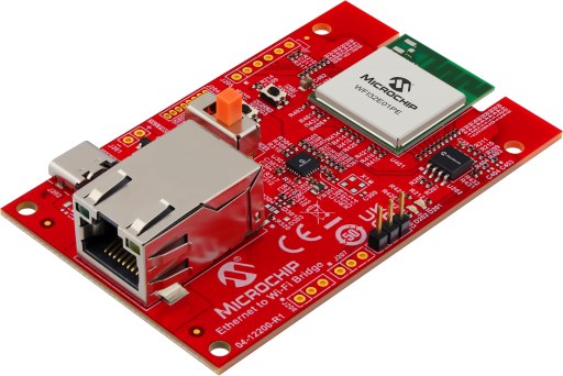
The Microchip EV49N51A Ethernet to Wi-Fi Bridge board
This page documents the NuttX port to the Microchip EV49N51A, the “Ethernet to Wi-Fi Bridge” reference design built around the WFI32E01PE Wi-Fi module. The module contains a PIC32MZ1025W104132 (PIC32MZ-W1 family) microcontroller.
Features
WFI32E01PE module (PCB antenna) with a PIC32MZ1025W104132:
MIPS32 M-Class core at 200 MHz
1 MB program flash, 256 KB data RAM
40 MHz crystal inside the module
2.4 GHz IEEE 802.11 b/g/n Wi-Fi (not supported by NuttX)
SST26VF032B 32 Mbit (4 MB) SPI serial flash (U202)
LAN8720A 10/100 Ethernet PHY (U301, RMII) with RJ45 connector J301
USB Type-C connector J202 (5 V power input only; the data lines are not connected) and MCP1727 3.3 V regulator
Debug UART header J203
Two user LEDs and one user button
ICSP header J204 (not fitted on the kit)
Supported hardware
Peripheral |
Status |
Notes |
|---|---|---|
UART1 |
Yes |
NSH console on J203 |
Timers |
Yes |
System tick |
GPIO |
Yes |
|
SPI1 |
Yes |
SST26VF032B; reads tested only |
I2C1/I2C2 |
Build |
Not tested; no I2C device on board |
Ethernet |
No |
|
Wi-Fi |
No |
Pin mapping
Module pads and chip pins as wired on the EV49N51A (schematic 02-01134 Rev 2):
Pin |
Signal |
Notes |
|---|---|---|
RA8 |
U1RX |
Debug UART, dedicated pin (not PPS) |
RA9 |
U1TX |
Debug UART, dedicated pin (not PPS) |
RK1 |
LED D201 (red) |
Active high |
RK3 |
LED D202 (green) |
Active high |
RA10 |
SW202 |
User button, low when pressed |
RA1 |
SST26 CS |
GPIO, active low |
RPC6 |
SPI1 SCK |
Dedicated SPI1 pin ( |
RPC7 |
SPI1 SDI |
Dedicated SPI1 pin |
RPC8 |
SPI1 SDO |
Dedicated SPI1 pin |
RB4 / RB5 |
PGC2 / PGD2 |
ICSP (J204), debug channel 2 |
RA4 / RA5 |
I2C1 |
GPIO header footprint (not fitted) |
The Ethernet PHY uses RPC9-RPC15, RPK6, RPK12-RPK14 and RPA14, but there is no Ethernet driver yet.
Clocking
Unlike the PIC32MZ EC/EF families, the PIC32MZ-W1 does not configure its
PLLs from the configuration words. At boot, pic32mz_wfi32_pwrclk.c:
On B0 silicon, after a power-on or brown-out reset, switches the power management unit (PMU) from its power-on MLDO mode to buck mode, using the factory trim values stored in the device.
CONFIG_PIC32MZ_W1_PMU_MLDO=yskips this step and keeps the PMU in MLDO mode.Starts the 40 MHz primary oscillator inside the module.
Programs the system PLL (40 MHz / 5 * 150 / 6 = 200 MHz) and the Ethernet/Wi-Fi PLL, and switches SYSCLK to the system PLL.
The peripheral bus clocks are set in include/board.h:
Clock |
Divider |
Frequency |
Used by |
|---|---|---|---|
PBCLK1 |
5 |
40 MHz |
Timers, UART3 |
PBCLK2 |
2 |
100 MHz |
I/O ports, I2C1, ADC, CAN |
PBCLK3 |
4 |
50 MHz |
UART1/2, SPI1/2, I2C2 |
PBCLK4 |
10 |
20 MHz |
RTCC, DSCON |
PBCLK5 |
2 |
100 MHz |
Flash, crypto, SQI |
PBCLK6 clocks the CPU on PIC32MZ-W1 and is not changed.
The program flash uses CONFIG_PIC32MZ_W1_FLASH_WAITSTATES wait states
(5 by default at 200 MHz).
Configuration words
The build places the configuration words (DEVCFG0/1/2/4, FBCFG0, FCPN0 and
FSIGN0) in nuttx.hex, so no separate configuration step is needed when
flashing. They are set through Kconfig (PIC32MZ_* options in
arch/mips/src/pic32mz/Kconfig). The nsh configuration selects ICSP
channel 2 (CONFIG_PIC32MZ_ICESEL_CH2) and keeps the secondary
oscillator disabled: the 32.768 kHz crystal X401 is not fitted on the kit.
Toolchains
The port builds with two toolchains:
CONFIG_MIPS32_TOOLCHAIN_PINGUINOL: the Pinguino p32-gcc toolchain, also used by the NuttX CI for all MIPS boards. It can be downloaded from https://github.com/PinguinoIDE/pinguino-compilers:$ curl -sSL -O https://github.com/PinguinoIDE/pinguino-compilers/releases/download/v20.10/pinguino-linux64-p32.zip $ unzip pinguino-linux64-p32.zip $ export PATH=$PWD/p32/bin:$PATH
CONFIG_MIPS32_TOOLCHAIN_MICROCHIPL_XC32: Microchip MPLAB XC32 for Linux (tested with v6.00), selected by thenshdefconfig.
XC32 v6 and later no longer include device support and need the
PIC32MZ-W Device Family Pack (DFP). Extract the
Microchip.PIC32MZ-W_DFP .atpack file (a zip archive) to
~/microchip/WFI32-W_DFP, or point WFI32E01_DFP_DIR at another
location:
$ make WFI32E01_DFP_DIR=/path/to/PIC32MZ-W_DFP
Flashing
The EV49N51A has no on-board programmer. The flash is programmed through the ICSP header J204 (MCLR, PGC2/RB4, PGD2/RB5, 3.3 V, GND), which is not fitted on the kit, using a Microchip programmer and MPLAB IPE. The port was tested with a PICkit 3:
$ cd /opt/microchip/mplabx/v6.20/mplab_platform/mplab_ipe
$ ./ipecmd.sh -P32MZ1025W104132 -TPPK3 -M -F/path/to/nuttx/nuttx.hex -Y -OL
-M programs the whole device, -Y verifies it and -OL releases
the device from reset. For other programmers, change -TPPK3 (for
example -TPPK4 for a PICkit 4).
Warning
Programming erases the factory firmware. Read it back first with MPLAB IPE if you want to restore it later.
Note
Debugging through a PICkit 3 does not work with this device
(MPLAB X marks PICkit 3 support for it as beta). Programming works.
For early boot problems, use CONFIG_PIC32MZ_W1_BOOTTRACE (see
below).
Configurations
Each configuration is built with:
$ ./tools/configure.sh -l ev49n51a:<config>
$ make
To build with the Pinguino toolchain instead of XC32:
$ ./tools/configure.sh -l ev49n51a:nsh
$ kconfig-tweak --disable MIPS32_TOOLCHAIN_MICROCHIPL_XC32 \
    --enable MIPS32_TOOLCHAIN_PINGUINOL
$ make olddefconfig
$ make
nsh
Basic NuttShell configuration with the console on UART1. Connect a 3.3 V USB-to-serial adapter to J203:
J203 pin |
Signal |
Adapter |
|---|---|---|
1 |
U1RX (RA8) |
TX |
2 |
U1TX (RA9) |
RX |
3 |
GND |
GND |
and open it at 115200 8N1, without flow control.
The SST26VF032B serial flash is registered as /dev/mtdblock0.
nsh> uname -a
NuttX 13.0.1-RC1 ec7277eeba Oct  3 2026 17:10:38 mips ev49n51a
nsh> ls -l /dev
/dev:
 crw-rw-rw-           0 console
 brw-rw-rw-     4194304 mtdblock0
 crw-rw-rw-           0 null
 crw-rw-rw-           0 ttyS0
 crw-rw-rw-           0 zero
Boot trace
CONFIG_PIC32MZ_W1_BOOTTRACE=y prints one character on UART1 for each
PMU and clock bring-up step, before the PLLs are running. UART1 is clocked
from the internal FRC during this phase, so the baud rate is about
117647 instead of 115200; most terminals still read it. The normal console
takes over once the clocks are up.
Silicon tested: WFI32E01PE, revision B0 (DEVID 0x0A400000).
Limitations
No Ethernet or Wi-Fi driver.
I2C1/I2C2 build but are not tested.
SPI flash: only reads were tested (JEDEC ID and data), not writes or erases.
UART3 is not wired up.
No button driver.