ESP32-C6-DevKitC-1
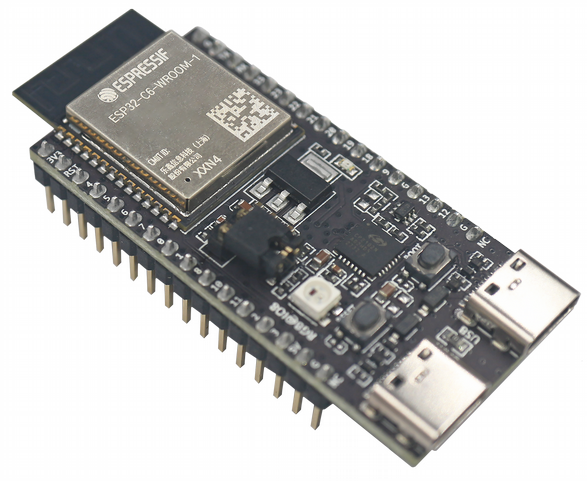
ESP32-C6-DevKitC-1 is an entry-level development board based on ESP32-C6-WROOM-1(U), a general-purpose module with a 8 MB SPI flash. This board integrates complete Wi-Fi, Bluetooth LE, Zigbee, and Thread functions. You can find the board schematic here.
Most of the I/O pins are broken out to the pin headers on both sides for easy interfacing. Developers can either connect peripherals with jumper wires or mount ESP32-C6-DevKitC-1 on a breadboard.
ESP32-C6-DevKitC-1 Board Layout
The block diagram below presents main components of the ESP32-C6-DevKitC-1.
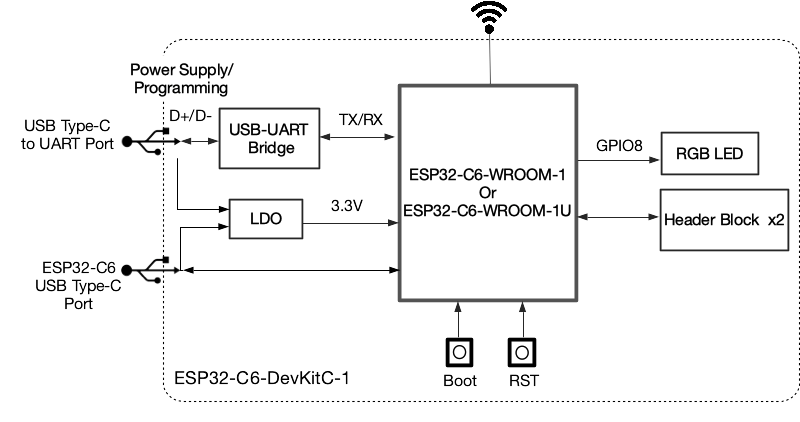
ESP32-C6-DevKitC-1 Electrical Block Diagram
Hardware Components
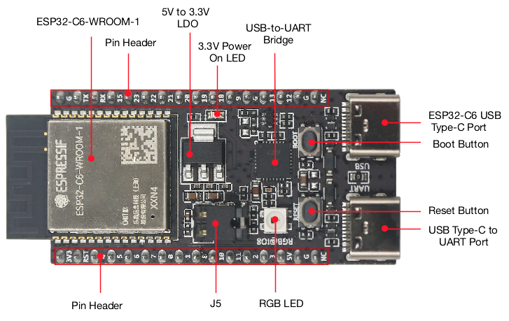
ESP32-C6-DevKitC-1 Hardware Components
Board LEDs
There is one on-board LED that indicates the presence of power. Another WS2812 LED is connected to GPIO8 and is available for software.
Current Measurement
The J5 headers on the ESP32-C6-DevKitC-1 can be used for measuring the current drawn by the ESP32-C6-WROOM-1(U) module:
Remove the jumper: Power supply between the module and peripherals on the board is cut off. To measure the module’s current, connect the board with an ammeter via J5 headers;
Apply the jumper (factory default): Restore the board’s normal functionality.
Note
When using 3V3 and GND pin headers to power the board, please remove the J5 jumper, and connect an ammeter in series to the external circuit to measure the module’s current.
Pin Mapping
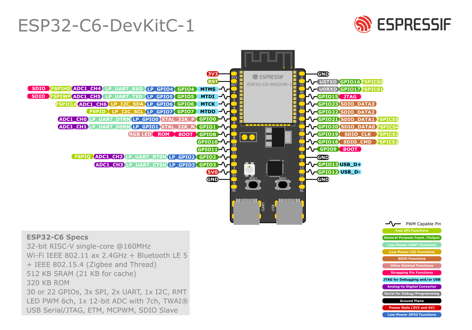
ESP32-C6-DevKitC-1 Pin Layout
Configurations
All of the configurations presented below can be tested by running the following commands:
$ ./tools/configure.sh esp32c6-devkit:<config_name>
$ make flash ESPTOOL_PORT=/dev/ttyUSB0 -j
Where <config_name> is the name of board configuration you want to use, i.e.: nsh, buttons, wifi…
Then use a serial console terminal like picocom configured to 115200 8N1.
coremark
This configuration sets the CoreMark benchmark up for running on the maximum number of cores for this system. It also enables some optimization flags and disables the NuttShell to get the best possible score.
Note
As the NSH is disabled, the application will start as soon as the system is turned on.
nsh
Basic configuration to run the NuttShell (nsh).