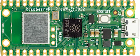
Raspberry Pi Pico W
The Raspberry Pi Pico is a general purpose board supplied by the Raspberry Pi Foundation. The W variant adds built in WiFi communications.
Features
RP2040 microcontroller chip
Dual-core ARM Cortex M0+ processor, flexible clock running up to 133 MHz
264kB of SRAM, and 2MB of on-board Flash memory
Castellated module allows soldering direct to carrier boards
USB 1.1 Host and Device support
Low-power sleep and dormant modes
Drag & drop programming using mass storage over USB
26 multi-function GPIO pins
2× SPI, 2× I2C, 2× UART, 3× 12-bit ADC, 16× controllable PWM channels
Accurate clock and timer on-chip
Temperature sensor
Accelerated floating point libraries on-chip
8 × Programmable IO (PIO) state machines for custom peripheral support
Built in WiFi radio (Infineon CYW43439)
Serial Console
By default a serial console appears on pins 1 (TX GPIO0) and pin 2 (RX GPIO1). This console runs a 115200-8N1.
The board can be configured to use the USB connection as the serial console.
Wireless Communication
The on board Infineon CYW43439 supports 2.4 GHz WiFi 4 communications (802.11n), WPS3 and SoftAP with up to four clients.
Pin Mapping
Pin |
Signal |
Notes |
|---|---|---|
1 |
GPIO0 |
Default TX for UART0 serial console |
2 |
GPIO1 |
Default RX for UART1 serial console |
3 |
Ground |
|
4 |
GPIO2 |
|
5 |
GPIO3 |
|
6 |
GPIO4 |
|
7 |
GPIO5 |
|
8 |
Ground |
|
9 |
GPIO6 |
|
10 |
GPIO7 |
|
11 |
GPIO8 |
|
12 |
GPIO9 |
|
13 |
Ground |
|
14 |
GPIO10 |
|
15 |
GPIO11 |
|
16 |
GPIO12 |
|
17 |
GPIO13 |
|
18 |
Ground |
|
19 |
GPIO14 |
|
20 |
GPIO15 |
|
21 |
GPIO16 |
|
22 |
GPIO17 |
|
23 |
Ground |
|
24 |
GPIO18 |
|
25 |
GPIO19 |
|
26 |
GPIO20 |
|
27 |
GPIO21 |
|
28 |
Ground |
|
29 |
GPIO22 |
|
30 |
Run |
|
31 |
GPIO26 |
ADC0 |
32 |
GPIO27 |
ADC1 |
33 |
AGND |
Analog Ground |
34 |
GPIO28 |
ADC2 |
35 |
ADC_VREF |
|
36 |
3V3 |
Power output to peripherals |
37 |
3V3_EN |
Pull to ground to turn off. |
38 |
Ground |
|
39 |
VSYS |
+5V Supply to board |
40 |
VBUS |
Connected to USB +5V |
Other RP2040 Pins
GPIO23 Output - WiFi controller enable. GPIO24 I/O - WiFi controller data line. GPIO25 Output - WiFi controller chip select line. GPIO29 Output - WiFi controller clock line. ADC3 Input - Analog voltage equal to one third of VSys voltage.
Note: ADC3 and GPIO29 share the same pin on the RP2040. If the GPIO25 line is held high (Wifi controller NOT selected) then a voltage equal to one third of the VSys voltage with appear on this line and can be read with ADC3. When the WiFi chip is selected this voltage will be removed so the line can be used as a clock for data exchange with the WiFi controller.
Separate pins for the Serial Debug Port (SDB) are available
WiFi Controller GPIO
GPIO0 - Output - On board LED. GPIO1 - Output - Power supply control. GPIO2 - Input - High if USB port or Pad 40 supplying power.
Power Supply
The Raspberry Pi Pico can be powered via the USB connector, or by supplying +5V to pin 39. The board had a diode that prevents power from pin 39 from flowing back to the USB socket, although the socket can be power via pin 30.
The Raspberry Pi Pico chip run on 3.3 volts. This is supplied by an onboard voltage regulator. This regulator can be disabled by pulling pin 37 to ground.
The regulator can run in two modes. By default the regulator runs in PFM mode which provides the best efficiency, but may be switched to PWM mode for improved ripple by outputting a one on the wireless chip’s GPIO1 (not the RP2040’s GPIO1).
Configurations
audiopack
NuttShell configuration (console enabled in UART0, at 115200 bps) with support for NSPlayer audio player.
composite
NuttShell configuration (console enabled in UART0, at 115200 bps) with support for CDC/ACM with MSC USB composite driver.
displaypack
NuttShell configuration (console enabled in USB Port, at 115200 bps) supporting ST7789 video display.
enc28j60
NuttShell configuration (console enabled in UART0, at 115200 bps) with support for NC28J60.
lcd1602
NuttShell configuration (console enabled in UART0, at 115200 bps) with support for LCD1602.
nsh
Basic NuttShell configuration (console enabled in UART0, at 115200 bps).
nsh-flash
Basic NuttShell configuration (console enabled in UART0, at 115200 bps with SMART flash filesystem.
nshsram
NuttShell configuration (console enabled in UART0, at 115200 bps) with interrupt vectors in RAM.
smp
Basic NuttShell configuration (console enabled in UART0, at 115200 bps) with both ARM cores enabled.
spisd
NuttShell configuration (console enabled in UART0, at 115200 bps) with SPI configured.
ssd1306
NuttShell configuration (console enabled in UART0, at 115200 bps) with support for ssd1306.
st7735
NuttShell configuration (console enabled in UART0, at 115200 bps) with support for st7735.
telnet
NuttShell configuration (console enabled in UART0, at 115200 bps) with WiFi client mode and both telnet server and client enabled.
After loading this configuration use make menuconfig to change the country code in Device Drivers->Wireless Device Support->IEEE 802.11 Device Support and the wireless configuration in Application Configuration->Network Utilities->Network initialization->WAPI Configuration to match your wireless network.
usbmsc
NuttShell configuration (console enabled in UART0, at 115200 bps) with support for usbmsc.
usbnsh
Basic NuttShell configuration (console enabled in USB Port, at 115200 bps).