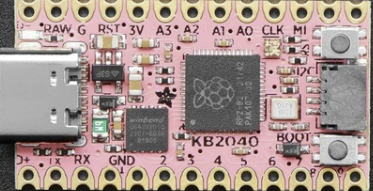
Adafruit KB2040 Key Boar
The KB2040 Key Boar is a general purpose RP2040 board supplied by Adafruit.
Features
RP2040 microcontroller chip
Dual-core ARM Cortex M0+ processor, flexible clock running up to 133 MHz
264kB of SRAM, and 8MB of on-board Flash memory
Castellated module allows soldering direct to carrier boards
USB Host and Device support via type C connector.
Low-power sleep and dormant modes
Drag & drop programming using mass storage over USB
18 multi-function GPIO pins
2× SPI, 2× I2C, 2× UART, 3× 12-bit ADC, 16× controllable PWM channels
Accurate clock and timer on-chip
Temperature sensor
Accelerated floating point libraries on-chip
8 × Programmable IO (PIO) state machines for custom peripheral support
On-board STEMMA QT connector for quick I2C connection.
Serial Console
By default a serial console appears on pins 1 (TX GPIO0) and pin 2 (RX GPIO1). This console runs a 115200-8N1.
The board can be configured to use the USB connection as the serial console.
Pin Mapping
Pads numbered anticlockwise from USB connector.
Pad |
Signal |
Notes |
|---|---|---|
1 |
D+ |
Alternate USB data connection. |
2 |
GPIO0 |
Default TX for UART0 serial console |
3 |
GPIO1 |
Default RX for UART1 serial console |
4 |
Ground |
|
5 |
Ground |
|
6 |
GPIO2 |
|
7 |
GPIO3 |
|
8 |
GPIO4 |
|
9 |
GPIO5 |
|
10 |
GPIO6 |
|
11 |
GPIO7 |
|
12 |
GPIO8 |
|
13 |
GPIO9 |
|
14 |
GPIO10 |
|
15 |
GPIO19 |
|
16 |
GPIO20 |
|
17 |
GPIO18 |
|
18 |
GPIO26 |
ADC0 |
19 |
GPIO27 |
ADC1 |
20 |
GPIO28 |
ADC2 |
21 |
GPIO29 |
ADC3 |
22 |
Ground |
|
23 |
Raw |
Connected to USB +5V line |
24 |
D- |
Alternate USB data connection. |
The board has a STEMMA QT connector that is also connected to pins GPI12 (I2C1 SDA) and GPI13 (I2C1 SDA).
Power Supply
The Raspberry Pi Pico can be powered via the USB connector, or by supplying +5V to pin 23.
The Raspberry Pi Pico chip run on 3.3 volts. This is supplied by an onboard voltage regulator.
Configurations
audiopack
NuttShell configuration (console enabled in UART0, at 115200 bps) with support for NSPlayer audio player.
composite
NuttShell configuration (console enabled in UART0, at 115200 bps) with support for CDC/ACM with MSC USB composite driver.
displaypack
NuttShell configuration (console enabled in USB Port, at 115200 bps) supporting ST7789 video display.
enc28j60
NuttShell configuration (console enabled in UART0, at 115200 bps) with support for NC28J60.
lcd1602
NuttShell configuration (console enabled in UART0, at 115200 bps) with support for LCD1602.
nsh
Basic NuttShell configuration (console enabled in UART0, at 115200 bps).
nsh-flash
Basic NuttShell configuration (console enabled in UART0, at 115200 bps with SMART flash filesystem.
nshsram
NuttShell configuration (console enabled in UART0, at 115200 bps) with interrupt vectors in RAM.
smp
Basic NuttShell configuration (console enabled in UART0, at 115200 bps) with both ARM cores enabled.
spisd
NuttShell configuration (console enabled in UART0, at 115200 bps) with SPI configured.
ssd1306
NuttShell configuration (console enabled in UART0, at 115200 bps) with support for ssd1306.
st7735
NuttShell configuration (console enabled in UART0, at 115200 bps) with support for st7735.
usbmsc
NuttShell configuration (console enabled in UART0, at 115200 bps) with support for usbmsc.
usbnsh
Basic NuttShell configuration (console enabled in USB Port, at 115200 bps).