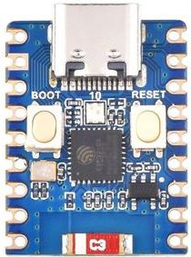
Waveshare ESP32-C3-Zero
The Waveshare ESP32-C3-Zero is a compact development board supplied by Waveshare.
Features
Low-power RISC-V 32-bit Single-core processor, up to 160MHz main frequency.
Supports 2.4GHz Wi-Fi (802.11 b/g/n) and Bluetooth® 5 (LE).
400KB SRAM, 384KB ROM and built-in 4MB flash memory.
15 multi-function GPIO pins.
3× SPI, 1× I2C, 2× UART, 1× I2S, 2× ADC.
Onboard WS2812 RGB led.
Compact SMD ceramic antenna.
Ultra-compact size: 23.5 × 18 mm
Pin Mapping
Pads numbered anticlockwise from USB connector.
Pad |
Signal |
Notes |
|---|---|---|
1 |
5V |
+5V Supply to board |
2 |
GND |
Ground |
3 |
3V3 |
Power output to peripherals |
4 |
GPIO0 |
|
5 |
GPIO1 |
|
6 |
GPIO2 |
|
7 |
GPIO3 |
|
8 |
GPIO4 |
SCK (bit-banging) |
9 |
GPIO5 |
MISO (bit-banging) |
10 |
GPIO6 |
MOSI (bit-banging) |
11 |
GPIO7 |
CSn (bit-banging) |
12 |
GPIO8 |
SCL (bit-banging) |
13 |
GPIO9 |
SDA (bit-banging) |
14 |
GPIO10 |
To connect with WS2812 RGB LED |
15 |
GPIO18 |
USB_D+ |
16 |
GPIO19 |
USB_D- |
17 |
GPIO20 |
Default RX for UART0 serial console |
18 |
GPIO21 |
Default TX for UART0 serial console |
Note
The Waveshare ESP32-C3-Zero does not have dedicated I2C and SPI pins. However, you can implement software-based I2C or SPI (bit-banging) using any available GPIO pins.
Power Supply
There are two mutually exclusive ways to provide power to the board:
USB Type-C Port
supplying via VIN (5V) pin (3.3–6 V) and GND pin headers
Installation & Build
For instructions on how to to install the build dependencies and create a NuttX image for this board, consult the main ESP32-C3 documentation.
Serial Console
A USB Serial Adapter is required to run NuttX on ESP32-C3-Zero with UART0 serial console.
Connect the USB Serial Adapter to ESP32-C3-Zero Serial Console at:
USB Serial |
ESP32-C3-Zero Pin |
|---|---|
GND |
GND (Pin 2) |
RX |
GPIO21 (UART0 TX) (Pin 18) |
TX |
GPIO20 (UART0 RX) (Pin 17) |
A USB serial adapter with +3.3V TTL level UART signals is required.
Connect ESP32-C3-Zero to our computer with the USB Serial Adapter. On our computer, start a Serial Terminal and connect to the USB Serial Port at 115200 bps.
NuttX will appear in the Serial Console when it boots on ESP32-C3-Zero.
Configurations
All configurations listed below can be configured using the following command in
the nuttx directory (again, consult the main ESP32-C3 documentation):
$ ./tools/configure.sh esp32-c3-zero:<config_name>
where <config_name> is the name of board configuration you want to use, i.e.: nsh, usbnsh, wifi…
Build System |
Support |
|---|---|
Make |
Yes |
CMake |
Yes |
$ make flash ESPTOOL_PORT=/dev/ttyUSB0 -j
Then use a serial console terminal like picocom configured to 115200 8N1.
jumbo
This configuration enables many Apache NuttX features (console enabled in UART0, at 115200 bps). This is mostly to help provide additional code coverage in CI, but also allows for a users to see a wide range of features that are supported by the OS.
I2C
The I2C Tool can be used to scan and manipulate I2C devices. You can scan for all I2C devices using the following command:
nsh> i2c dev -b 3 00 77
NOTE: Some devices may not appear with this scan.
You may also try a scan with the -z flag to discover more devices using a zero-byte write request.
     0  1  2  3  4  5  6  7  8  9  a  b  c  d  e  f
00: -- -- -- -- -- -- -- -- -- -- -- -- -- -- -- --
10: -- -- -- -- -- -- -- -- -- -- -- -- -- -- -- --
20: -- -- -- -- -- -- -- -- -- -- -- -- -- -- -- --
30: -- -- -- -- -- -- -- -- -- -- -- -- -- -- -- --
40: -- -- -- -- -- -- -- -- -- -- -- -- -- -- -- --
50: -- -- -- -- -- -- -- -- -- -- -- -- -- -- -- --
60: -- -- -- -- -- -- -- -- -- -- -- -- -- -- -- --
70: -- -- -- -- -- -- 76 --
nsh>
Tip
Please refer to I2C Tool for more information.
SPI
The SPI Tool provides a way to debug SPI related problems.
You can test it by connecting MOSI and MISO pins which are GPIO6 and GPIO5
by default to each other and running the spi example:
nsh> spi exch -b 3 "AB"
Sending:    AB
Received:   AB
Tip
Please refer to SPI Tool for more information.
bmp280
You can check that the Bosch BMP280 sensor over I2C is working by using the bmp280 application:
BMP280 |
ESP32-C3-Zero Pin |
|---|---|
VCC |
3V3 OUT (Pin 3) |
GND |
GND (Pin 2) |
SCL |
GPIO8 (SCL) (Pin 12) |
SDA |
GPIO9 (SDA) (Pin 13) |
nsh> bmp280
Absolute pressure [hPa] = 1003.359985
Temperature [C] = 18.969999
sensortest
You can check that the Bosch BMP280 sensor over I2C is working by using the sensortest application:
nsh> sensortest -n 10 baro0
SensorTest: Test /dev/uorb/sensor_baro0 with interval(1000000us), latency(0us)
baro0: timestamp:3449690000 value1:1023.23 value2:19.75
baro0: timestamp:3449690000 value1:1023.23 value2:19.75
baro0: timestamp:3449690000 value1:1023.23 value2:19.75
baro0: timestamp:3449690000 value1:1023.23 value2:19.75
baro0: timestamp:3449690000 value1:1023.23 value2:19.75
baro0: timestamp:3449700000 value1:1023.23 value2:19.75
baro0: timestamp:3449700000 value1:1023.23 value2:19.75
baro0: timestamp:3449710000 value1:1022.82 value2:19.86
baro0: timestamp:3449710000 value1:1022.82 value2:19.86
baro0: timestamp:3449720000 value1:1022.82 value2:19.86
SensorTest: Received message: baro0, number:10/10
nsh>
nsh
Basic configuration that runs NuttShell (console enabled in UART0, at 115200 bps). This configuration is focused on low level, command-line driver testing. Built-in applications are supported, but none are enabled.
Tip
Please refer to NuttShell (NSH) for more information.
sta_softap
With this configuration you can run these commands to be able to connect your smartphone or laptop to your board:
nsh> ifup wlan1
nsh> dhcpd_start wlan1
nsh> wapi psk wlan1 mypasswd 3
nsh> wapi essid wlan1 nuttxap 1
In this case, you are creating the access point nuttxapp in your board and to
connect to it on your smartphone you will be required to type the password mypasswd
using WPA2.
Tip
Please refer to ESP32 Wi-Fi SoftAP Mode for more information.
The dhcpd_start is necessary to let your board to associate an IP to your smartphone.
usbnsh
Basic NuttShell configuration using CDC/ACM serial (console enabled in USB Port, at 115200 bps). This is another NSH example. If differs from other ‘nsh’ configurations in that this configurations uses a USB serial device for console I/O.
wifi
Enables Wi-Fi support. You can define your credentials this way:
$ make menuconfig
-> Application Configuration
    -> Network Utilities
        -> Network initialization (NETUTILS_NETINIT [=y])
            -> WAPI Configuration
Or if you don’t want to keep it saved in the firmware you can do it at runtime:
nsh> wapi psk wlan0 mypasswd 3
nsh> wapi essid wlan0 myssid 1
nsh> renew wlan0
Tip
Please refer to ESP32 Wi-Fi Station Mode for more information.