RZV2H-EVK

Tags: arch:arm arch:armv7-r arch:cortex-r8 chip:rzv2h vendor:renesas

The RZV2H-EVK is an evaluation board for the Renesas RZ/V2H (R9A09G057) MPU. NuttX is ported to run on one of the two Cortex-R8 real-time cores (CR8_0).

Board Overview
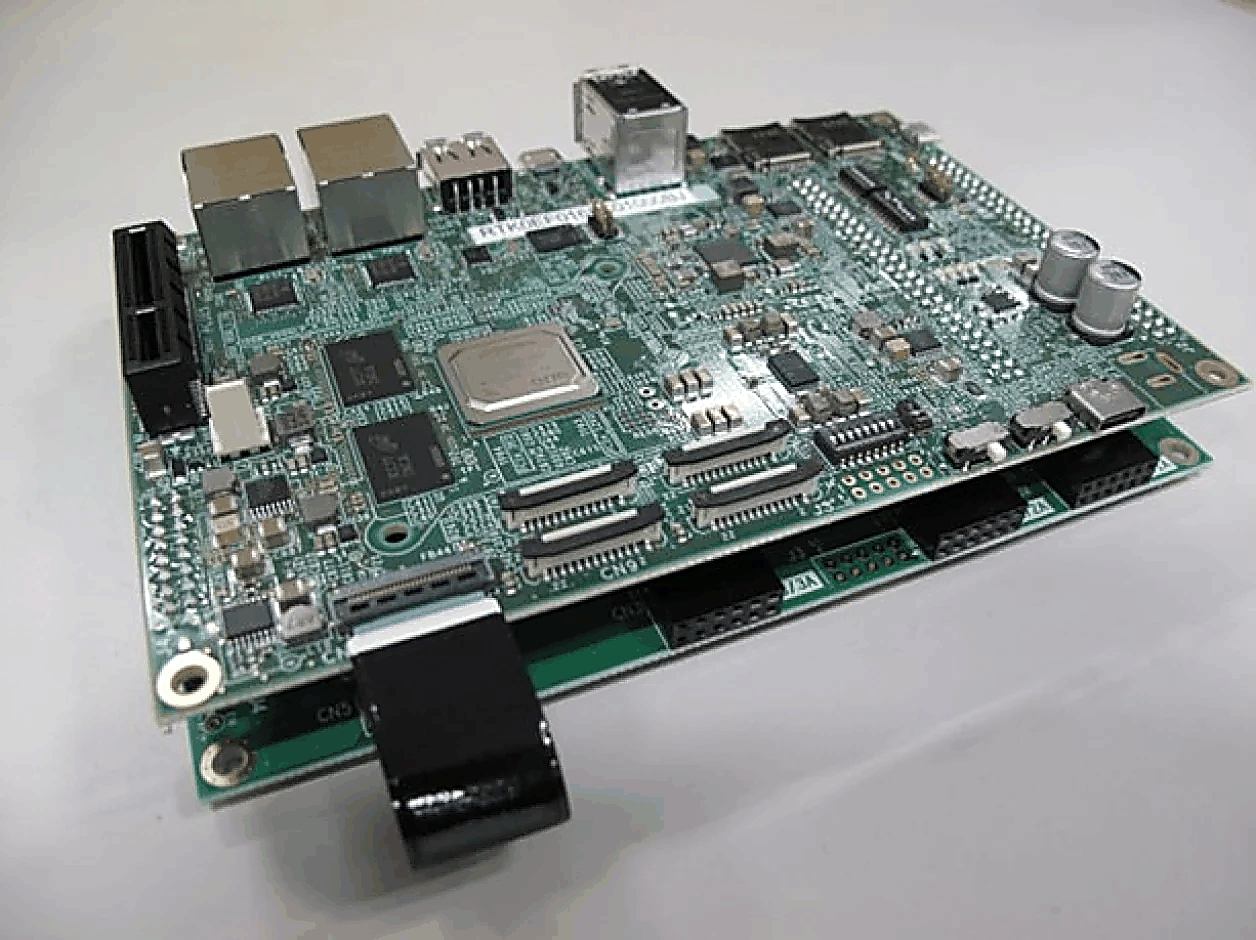
../../../../../_images/rzv2h-evk-overview.png

See the RZ/V2H product page for information about the RZ/V2H MPU.

Board Set-up
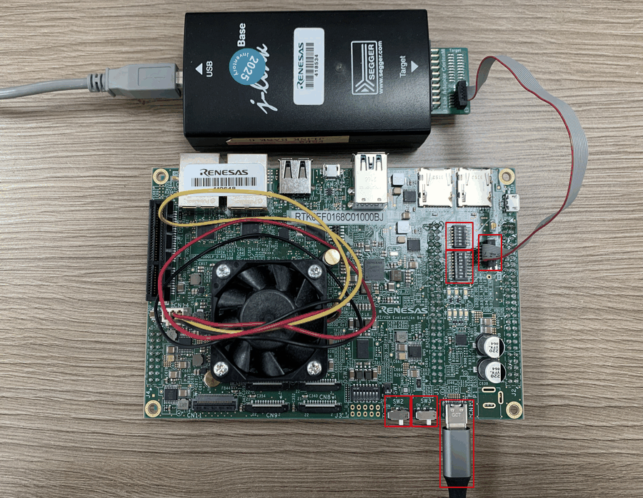
../../../../../_images/rzv2h-evk-board-set-up.png

The following steps set up the board to debug/run NuttX over SWD with a J-Link debugger:

  1. Configure the SWD interface to use the J-Link debugger via the DIP switches (highlighted in red in the picture above):

    DSW 1

    Set

    DSW 2

    Set

    1-1

    ON

    2-1

    OFF

    1-2

    OFF

    2-2

    OFF

    1-3

    ON

    2-3

    OFF

    1-4

    OFF

    2-4

    OFF

    1-5

    ON

    2-5

    OFF

    1-6

    OFF

    2-6

    OFF

    1-7

    ON

    1-8

    OFF

  2. Connect CN1 to the J-Link debugger.

  3. Make sure SW2 and SW3 are OFF before connecting CN13 to the power supply.

  4. After CN13 is connected to the power supply, turn SW3 ON first, then turn SW2 ON.

To power off the board, reverse the order: disconnect the J-Link debugger first, then turn SW2 OFF, then SW3 OFF, and only then remove power.

Getting the HAL Renesas

Clock bring-up (see below) is implemented on top of Renesas’ vendored FSP BSP code, which ships in a separate hal_renesas repository and is not part of the nuttx git tree.

make context (run automatically as part of a normal build) clones the repository at the pinned version into arch/arm/src/common/renesas/hal_renesas, as defined in arch/arm/src/common/renesas/Make.defs. Nothing needs to be cloned manually. make distclean removes it.

HAL_RENESAS_URL and HAL_RENESAS_VERSION can be set in the environment to use another repository or revision, for example a local checkout:

HAL_RENESAS_URL=/path/to/hal_renesas make

Buttons and LEDs

Buttons

The RZ/V2H-EVK has no dedicated user button. The board port reserves P8_2 for one external, active-high button and exposes it through the generic NuttX GPIO interface as /dev/gpio0. It does not currently provide a discrete NuttX button device such as /dev/buttons.

Hardware connection

Locate P8_2 on the selected expansion connector using the RZ/V2H-EVK schematic. Connect a normally-open momentary switch between P8_2 and the board’s 3.3-V logic supply, with a common ground between the board and the external circuit. The board configures P8_2 as an input with its internal pull-down enabled:

  • button released: the pull-down drives the input low; /dev/gpio0 reads 0;

  • button pressed: the switch drives the input high; /dev/gpio0 reads 1.

The pin definition is BOARD_P8_2_BUTTON in boards/arm/rzv2h/rzv2h-evk/include/board.h. It selects BSP_IO_PORT_08_PIN_02 with input, input-buffer, and pull-down settings.

Warning

P8_2 is a multiplexed pin. Confirm the EVK schematic and make sure that no enabled peripheral claims this pin before connecting the button.

Configuration and registration

Use a configuration that enables the generic GPIO test path, for example rzv2h-evk:nsh-leds. The required options are:

CONFIG_DEV_GPIO=y
CONFIG_RZV2H_GPIO=y
CONFIG_EXAMPLES_GPIO=y
CONFIG_BOARD_LATE_INITIALIZE=y

During board_late_initialize(), rzv2h_bringup() calls rzv2h_gpio_initialize(). This registers the one input first as /dev/gpio0 and configures the input through the Renesas FSP IOPORT driver. CONFIG_RZV2H_GPIO defaults to enabled when CONFIG_DEV_GPIO is selected, but it is shown above to make the dependency explicit.

NSH usage example

After booting NuttX, first verify that the device was registered:

nsh> ls /dev
nsh> gpio /dev/gpio0
Driver: /dev/gpio0
  Input pin:     Value=0

Press and hold the button, then run the read command again:

nsh> gpio /dev/gpio0
Driver: /dev/gpio0
  Input pin:     Value=1

Release the button and repeat the command; the value must return to 0. Each invocation of the standard apps/examples/gpio application performs one read and exits, so the button must remain pressed for the second command.

Current limitations

The current GPIO implementation supports synchronous read and write only. GPIO interrupt attachment and enablement are placeholders, so gpio -w cannot report button transitions. Runtime pin-type changes are also not implemented, so do not use gpio -t. The board does not debounce the external switch; use a polling application with software debounce if continuous monitoring is required.

LEDs

Two active-low GPIO outputs are available for LED testing. They are registered after the button input, giving the following device mapping:

Pin

GPIO device

Function

P0_0

/dev/gpio1

LED output 1

P0_1

/dev/gpio2

LED output 2

Using the NSH GPIO application

The nsh configuration enables CONFIG_DEV_GPIO and CONFIG_EXAMPLES_GPIO. The gpio example is reused from the standard NuttX application repository at apps/examples/gpio; it is not an RZ/V2H-specific application. The RZ/V2H board port only configures the pins, registers /dev/gpio0 through /dev/gpio2, and enables the example in the board configuration. The upstream example source is used without board-specific polling logic.

The GPIO application uses the following command format:

gpio [-t <pintype>] [-w <signo>] [-o <value>] <driver-path>

Note

At this stage, the RZ/V2H GPIO driver supports only GPIO read and write operations for application testing. Changing the pin type is not supported: GPIOC_SETPINTYPE does not reconfigure the hardware. GPIO interrupt attachment and enablement are also placeholders, so interrupt notification is not available.

Consequently, use only gpio <driver-path> for reading and gpio -o <0|1> <driver-path> for writing. Do not use the -t pin-type option or the -w interrupt-wait option on this board.

For these LED outputs, only -o and the device path are needed. The -o option writes the logical pin level (zero or one), while the device path selects the LED. Because the LEDs are active low, write zero to turn an LED on and one to turn it off. For example:

nsh> gpio -o 0 /dev/gpio1
nsh> gpio -o 1 /dev/gpio1
nsh> gpio -o 0 /dev/gpio2
nsh> gpio -o 1 /dev/gpio2

For each command, the application reports the previous output level, the level being written, and the level read back from the driver. For example, if LED output 1 is currently off:

nsh> gpio -o 0 /dev/gpio1
Driver: /dev/gpio1
  Output pin:    Value=1
  Writing:       Value=0
  Verify:        Value=0

Omit -o to read the current output level without changing it:

nsh> gpio /dev/gpio1

Each invocation performs a single GPIO operation and then exits. This is sufficient for the manual button and LED validation described here.

Use gpio -h to display the generic application’s command syntax. Some options shown by that help text are not yet supported by the RZ/V2H GPIO driver, as described above.

Using the NuttX user-LED application

The nsh-leds configuration also enables the standard NuttX user-LED interface and example with these options:

# CONFIG_ARCH_LEDS is not set
CONFIG_USERLED=y
CONFIG_USERLED_LOWER=y
CONFIG_EXAMPLES_LEDS=y
CONFIG_BOARD_LATE_INITIALIZE=y

During late initialization, the board registers /dev/userleds. The board_userled_*() callbacks configure P0_0 and P0_1, convert the logical LED state to the active-low pin level, and support LED mask bits 0x01 and 0x02.

Run the unmodified NuttX example from apps/examples/leds to cycle the two LED outputs:

nsh> ls /dev
nsh> leds

The device list should contain userleds, and the example should report a supported LED mask of 0x03. The leds command starts a background led_daemon that cycles the LED mask. Its startup message prints the daemon PID; use kill <pid> to stop it.

This interface is separate from the generic /dev/gpio1 and /dev/gpio2 devices. Use the gpio example for individual read/write validation, or use the leds example to exercise the NuttX user-LED API. Automatic OS-status LED control through CONFIG_ARCH_LEDS is not yet implemented.

Application test responsibilities

The current button and LED tests both reuse the standard NuttX GPIO example:

Test

Application source

Responsibility

Button read test

Standard NuttX apps/examples/gpio application

Press and hold the button, then read /dev/gpio0

LED read/write test

Standard NuttX apps/examples/gpio application

Reused unchanged; the board port only configures and registers the LED GPIO devices

User-LED sequence test

Standard NuttX apps/examples/leds application

Reused unchanged; it controls both active-low outputs through /dev/userleds

Important

No RZ/V2H-specific test application is required for the current manual validation. Use the standard NuttX gpio example to read the button through /dev/gpio0 and to control the LEDs through /dev/gpio1 and /dev/gpio2. A separate polling application is needed only if continuous monitoring, transition detection, or debounce testing is required later.

The GPIO devices are registered from the board late-initialization path, so CONFIG_BOARD_LATE_INITIALIZE must remain enabled.

The user-controlled board_userled_*() hooks and /dev/userleds are supported. The automatic board_autoled_*() hooks selected by CONFIG_ARCH_LEDS remain placeholders.

Serial Consoles

The default nsh configuration uses SCI channel 0 as the serial console at 115200 baud, 8 data bits, no parity, and one stop bit. The board pin definitions route SCI0 as follows:

Signal

Pin

Board definition

TXD0

P5_0

BOARD_SCI0_TXD_GPIO

RXD0

P5_1

BOARD_SCI0_RXD_GPIO

Connect the USB-to-UART adapter to the CN3 Pmod contacts shown below:

CN3 pin

CN3 signal

SoC pin

USB-to-UART connection

1

CTS

P52

RTS (Unused)

2

TXD0

P50

RX

3

RXD0

P51

TX

4

RTS

P53

CTS (Unused)

5

GND

–

GND

6

VCC

–

VCC

7

IO1

P57

Unused

8

IO2

P73

Unused

9

IO3

P76

Unused

10

IO4

P77

Unused

11

GND

–

Unused

12

VCC

–

Unused

Cross the data lines so that CN3 TXD0 connects to the adapter RX and CN3 RXD0 connects to the adapter TX. Hardware flow control is not enabled, so CTS and RTS remain disconnected. Use a 3.3 V TTL UART adapter, not an RS-232 adapter. The table assumes that the adapter is powered through USB; do not connect either CN3 VCC contact to the adapter.

The relevant default options are:

CONFIG_RZV2H_UART_SCI=y
CONFIG_RZV2H_SCI_B_UART0=y
CONFIG_SCI0_SERIAL_CONSOLE=y
CONFIG_SCI0_BAUD=115200
CONFIG_SCI0_BITS=8
CONFIG_SCI0_PARITY=0
CONFIG_SCI0_2STOP=0

After boot, SCI0 is available as both /dev/console and /dev/ttyS0. The terminal should display the NuttX banner followed by the nsh> prompt. Verify the registration with:

nsh> ls /dev
/dev:
 console
 null
 ttyS0
 zero

Additional enabled SCI channels are registered as later /dev/ttyS* devices in ascending hardware-channel order. Their TX and RX pin choices are board-specific and are defined by BOARD_SCIn_TXD_GPIO and BOARD_SCIn_RXD_GPIO in boards/arm/rzv2h/rzv2h-evk/include/board.h.

Bring-up

This section describes what has been brought up so far for the CR8_0 core. Clock, MPU, GIC, timer, GPIO, and SCI-B UART support described on this page are implemented. Board options not described here may still be placeholders.

Clock control

rzv2h_clockconfig() (arch/arm/src/rzv2h/rzv2h_clockconfig.c) calls into bsp_clock_init() from the vendored Renesas FSP BSP (arch/arm/src/common/renesas/hal_renesas/...), which programs the PLL and clock tree. The system tick timer (see Timer below) derives its input clock from the resulting BSP_CFG_CLOCK_I6CLK_HZ value, so this must run before the timer is configured.

MPU enablement

arch/arm/src/rzv2h/rzv2h_mpu_region.c defines a static PMSAv7 region table (g_mpu_region_table[]) for CR8 core 0:

  • Region 0 - ITCM (0x00000000, 128 KB), read-only, holds the exception vector table copied there by arm_boot().

  • Region 1 - DTCM (0x00020000, 128 KB), read/write, execute-never.

  • Region 2 - RCPU-SRAM (cacheable), read/write, execute-never default for the whole image range.

  • Last region - the read-only code window (__mpu_code_start .. __mpu_code_end, provided by the linker script), read-only and executable, layered on top of region 2 so code remains executable while data stays non-executable.

Because PMSAv7 lets the highest-numbered matching region win, the executable code window must be the last entry in the table, and its size must be padded to a power of two by the linker script to satisfy PMSAv7’s size/alignment rule.

Interrupt initialization

up_irqinitialize() (arch/arm/src/rzv2h/rzv2h_irq.c) brings up the Generic Interrupt Controller (GIC): arm_gic0_initialize() runs once, on CPU0 only, followed by arm_gic_initialize() on every CPU. Interrupts are then unmasked with up_irq_enable().

Beyond the GIC’s fixed interrupt lines, the CR8 core’s INTC also exposes a pool of 127 programmable “SEL” lines used by peripherals and the TINT pin-interrupt controller.

Timer

arch/arm/src/rzv2h/rzv2h_timerisr.c uses the Arm MPCore Private Timer as the system tick source. Its clock is BSP_CFG_CLOCK_I6CLK_HZ / 2, and the reload value is derived from CLK_TCK so the timer fires every system tick. The Private Timer interrupt (BSP IRQn -3) maps to GIC INTID 29.

Loading Code

Use a J-Link or another SWD/JTAG probe to load debugger configurations.

Configurations

nsh

NuttShell configuration exercising clock, MPU, interrupt/timer, GPIO, and SCI-B UART bring-up on CR8_0. SCI0 provides the default 115200-8N1 NSH console through CN3 and is registered as /dev/console and /dev/ttyS0.

nsh-leds

This configuration enables CONFIG_USERLED, registers /dev/userleds, and includes the standard NuttX leds example. Run leds to cycle the active-low P0_0 and P0_1 LED outputs. The generic /dev/gpio1 and /dev/gpio2 interfaces are also available for individual read/write testing. Automatic OS-status LED control through CONFIG_ARCH_LEDS is not yet implemented.