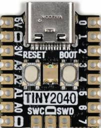
Pimoroni Tiny2040
The Tiny2040 is a general purpose RP2040 board supplied by Pimoroni.
Features
RP2040 microcontroller chip
Dual-core ARM Cortex M0+ processor, flexible clock running up to 133 MHz
264kB of SRAM, and 2MB or 8MB of on-board Flash memory
Castellated module allows soldering direct to carrier boards
USB Host and Device support via type C connector
Low-power sleep and dormant modes
Drag & drop programming using mass storage over USB
12 multi-function GPIO pins
2× SPI, 2× I2C, 2× UART, 3× 12-bit ADC, 16× controllable PWM channels
Accurate clock and timer on-chip
Temperature sensor
Accelerated floating point libraries on-chip
8 × Programmable IO (PIO) state machines for custom peripheral support
Serial Console
By default a serial console appears on pins 15 (RX GPIO0) and pin 16 (TX GPIO1). This console runs a 115200-8N1.
The board can be configured to use the USB connection as the serial console.
Pin Mapping
Pads numbered anticlockwise from USB connector.
Pad |
Signal |
Notes |
|---|---|---|
1 |
VBUS |
Connected to USB +5V |
2 |
Ground |
|
3 |
3V3 |
Out to peripherals |
4 |
GPIO29 |
ADC3 |
5 |
GPIO28 |
ADC2 |
6 |
GPIO27 |
ADC1 |
7 |
GPIO26 |
ADC0 |
8 |
Ground |
|
9 |
GPIO7 |
|
10 |
GPIO6 |
|
11 |
GPIO5 |
|
12 |
GPIO4 |
|
13 |
GPIO3 |
|
14 |
GPIO2 |
|
15 |
GPIO1 |
Default RX for UART0 serial console |
16 |
GPIO0 |
Default TX for UART0 serial console |
Power Supply
The Raspberry Pi Pico can be powered via the USB connector, or by supplying +5V to pin 1.
The Raspberry Pi Pico chip run on 3.3 volts. This is supplied by an onboard voltage regulator.
Configurations
composite
NuttShell configuration (console enabled in UART0, at 115200 bps) with support for CDC/ACM with MSC USB composite driver.
gpio
NuttShell configuration (console enabled in UART0, at 115200 bps) with GPIO examples.
nsh
Basic NuttShell configuration (console enabled in UART0, at 115200 bps).
nsh-flash
Basic NuttShell configuration (console enabled in UART0, at 115200 bps with SMART flash filesystem.
nshsram
NuttShell configuration (console enabled in UART0, at 115200 bps) with interrupt vectors in RAM.
smp
Basic NuttShell configuration (console enabled in UART0, at 115200 bps) with both ARM cores enabled.
spisd
NuttShell configuration (console enabled in UART0, at 115200 bps) with SPI configured.
usbmsc
NuttShell configuration (console enabled in UART0, at 115200 bps) with support for usbmsc.
usbnsh
Basic NuttShell configuration (console enabled in USB Port, at 115200 bps).
README.txt
README
======

This directory contains the port of NuttX to the Pimoroni Tiny 2040.
See https://shop.pimoroni.com/products/tiny-2040?variant=39560012234835
for information about Pimoroni Tiny 2040.

The Pimoroni Tiny 2040 has two buttons (RESET and BOOT) allowing to boot
from ROM without disconnecting the device.

NuttX supports the following RP2040 capabilities:
  - UART  (console port)
    - GPIO 0 (UART0 TX) and GPIO 1 (UART0 RX) are used for the console.
  - I2C (not tested on Tiny 2040)
  - SPI (master only)
  - DMAC
  - PWM
  - ADC
  - Watchdog
  - USB device
    - MSC, CDC/ACM serial and these composite device are supported.
    - CDC/ACM serial device can be used for the console.
  - PIO (RP2040 Programmable I/O)
  - Flash ROM Boot
  - SRAM Boot
    - If Pico SDK is available, nuttx.uf2 file which can be used in
      BOOTSEL mode will be created.
  - Persistent flash filesystem in unused flash ROM

NuttX also provide support for these external devices:

  - WS2812 smart pixel support

There is currently no direct user mode access to these RP2040 hardware features:
  - SPI Slave Mode
  - SSI
  - RTC
  - Timers

Installation
============

1. Download Raspberry Pi Pico SDK

  $ git clone -b 1.1.2 https://github.com/raspberrypi/pico-sdk.git

2. Set PICO_SDK_PATH environment variable

  $ export PICO_SDK_PATH=<absolute_path_to_pico-sdk_directory>

3. Configure and build NuttX

  $ git clone https://github.com/apache/nuttx.git nuttx
  $ git clone https://github.com/apache/nuttx-apps.git apps
  $ cd nuttx
  $ make distclean
  $ ./tools/configure.sh pimoroni-tiny2040:nsh
  $ make V=1

4. Connect Pimoroni Tiny 2040 board to USB port. While pressing the
   BOOT button, shortly press the RESET button. On releasing the BOOT
   button the board boots from internal ROM and will be detected as
   USB Mass Storage Device. Then copy "nuttx.uf2" into the device.
   (Same manner as the standard Pico SDK applications installation.)

5. To access the console, GPIO 0 and 1 pins must be connected to the
   device such as USB-serial converter.

   `usbnsh` configuration provides the console access by USB CDC/ACM serial
   devcice.  The console is available by using a terminal software on the USB
   host.

Defconfigs
==========

- nsh
    Minimum configuration with NuttShell

- nsh-flash
    NuttX shell with SMART flash filesystem.

- nshsram
    Load NuttX binary to SRAM

- smp
    Enable SMP mode. Both Core 0 and Core 1 are used by NuttX.

- spisd
    SD card support (SPI connection)
    Connection:
      SD card slot    ----- Pimoroni Tiny 2040
      (Pin 9) DAT2          (NC)
      (Pin 1) DAT3/CS ----- GP5 (SPI0 CSn) (Pin 11)
      (Pin 2) CMD /DI ----- GP7 (SPI0 TX)  (Pin 9)
      (Pin 3) VSS     ----- GND            (Pin 2 or 8)
      (Pin 4) VDD     ----- 3V3 OUT        (Pin 3)
      (Pin 5) CLK/SCK ----- GP6 (SPI0 SCK) (Pin 10)
      (Pin 6) VSS     ----- GND            (Pin 2 or 8)
      (Pin 7) DAT0/DO ----- GP4 (SPI0 RX)  (Pin 12)
      (Pin 8) DAT1          (NC)
    * Card hot swapping is not supported.

- usbnsh
    USB CDC/ACM serial console with NuttShell

- usbmsc
    USB MSC and CDC/ACM support
    `msconn` and `sercon` commands enable the MSC and CDC/ACM devices.
    The MSC support provides the interface to the SD card with SPI,
    so the SD card slot connection like spisd configuration is required.

- composite
    USB composite device (MSC + CDC/ACM) support
    `conn` command enables the composite device.

- gpio
    GPIO driver and example application 'gpio' based on nsh configuration.
    Following GPIO are configured in include/board.h:
      GPIO18 (out): onboard RGB LED (red)
      GPIO19 (out): onboard RGB LED (green)
      GPIO20 (out): onboard RGB LED (blue)
      GPIO23 (in) : onboard BOOT (USER) button
    * No interrupt pin configured.

License exceptions
==================

The following files are originated from the files in Pico SDK.
So, the files are licensed under 3-Clause BSD same as Pico SDK.

- arch/arm/src/rp2040/rp2040_clock.c
- arch/arm/src/rp2040/rp2040_pll.c
- arch/arm/src/rp2040/rp2040_xosc.c
  - These are created by referring the Pico SDK clock initialization.

- arch/arm/src/rp2040/rp2040_pio.c
- arch/arm/src/rp2040/rp2040_pio.h
- arch/arm/src/rp2040/rp2040_pio_instructions.h
  - These provide the similar APIs to Pico SDK's hardware_pio APIs.

- arch/arm/src/rp2040/hardware/*.h
  - These are generated from rp2040.svd originally provided in Pico SDK.