ESP32-Ethernet-Kit V1.2
The ESP32-Ethernet-Kit is an Ethernet-to-Wi-Fi development board that enables Ethernet devices to be interconnected over Wi-Fi. At the same time, to provide more flexible power supply options, the ESP32-Ethernet-Kit also supports power over Ethernet (PoE). You can find the board schematic here.
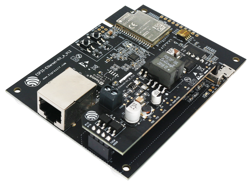
ESP32-Ethernet-Kit V1.2 Board Layout
It consists of two development boards, the Ethernet board A and the PoE board B. The Ethernet board (A) contains Bluetooth/Wi-Fi dual-mode ESP32-WROVER-E module and IP101GRI, a Single Port 10/100 Fast Ethernet Transceiver (PHY). The PoE board (B) provides power over Ethernet functionality. The A board can work independently, without the board B installed.
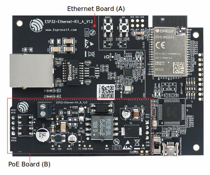
ESP32-Ethernet-Kit V1.2
For the application loading and monitoring, the Ethernet board (A) also features FTDI FT2232H chip - an advanced multi-interface USB bridge. This chip enables to use JTAG for direct debugging of ESP32 through the USB interface without a separate JTAG debugger.
The block diagram below presents main components of the ESP32-Ethernet-Kit.
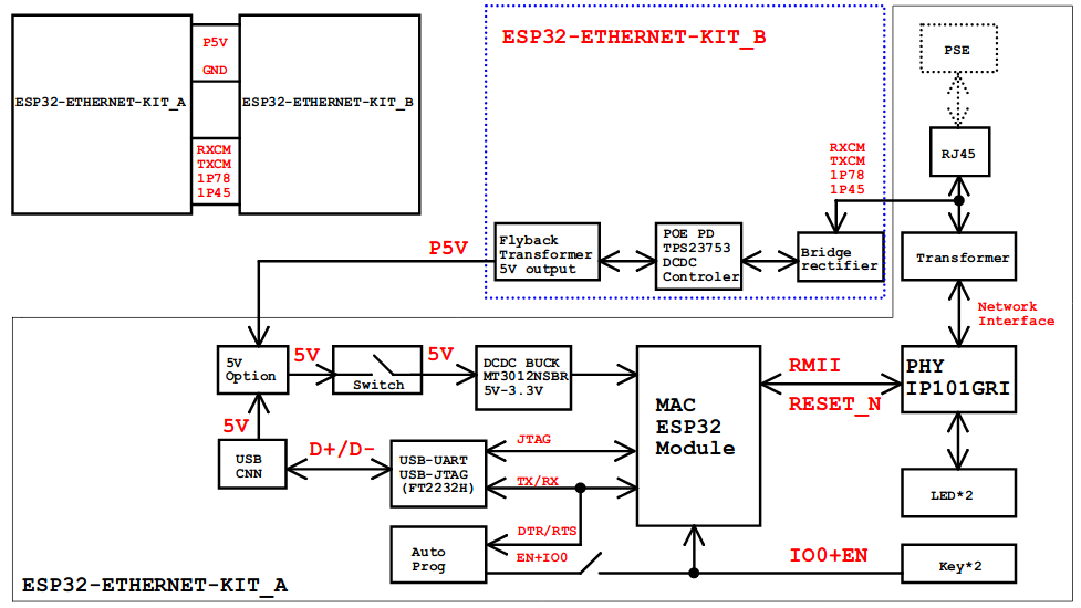
ESP32-Ethernet-Kit V1.2 Electrical Block Diagram
The ESP32 is a dual-core system from Espressif with two Harvard architecture Xtensa LX6 CPUs. All embedded memory, external memory and peripherals are located on the data bus and/or the instruction bus of these CPUs. With some minor exceptions, the address mapping of two CPUs is symmetric, meaning they use the same addresses to access the same memory. Multiple peripherals in the system can access embedded memory via DMA.
The ESP32-Ethernet-Kit is an Ethernet-to-Wi-Fi development board that enables Ethernet devices to be interconnected over Wi-Fi. At the same time, to provide more flexible power supply options, the ESP32-Ethernet-Kit also supports power over Ethernet (PoE).
Features
ESP32-WROVER-E Module
JTAG through USB
Ethernet
Power over Ethernet (PoE)
USB-to-UART bridge via micro USB port
Functional Description
The following figures describe the key components, interfaces, and controls of the ESP32-Ethernet-Kit.
Ethernet Board (A)
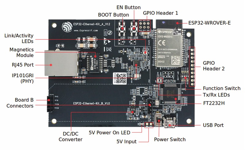
ESP32-Ethernet-Kit - Ethernet board (A) layout
PoE Board (B)
This board converts power delivered over the Ethernet cable (PoE) to provide a power supply for the Ethernet board (A). The main components of the PoE board (B) are shown on the image below.
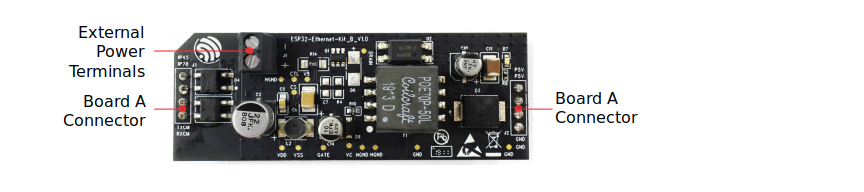
ESP32-Ethernet-Kit - PoE board (B) layout
The PoE board (B) has the following features:
Support for IEEE 802.3at
Power output: 5 V, 1.4 A
To take advantage of the PoE functionality the RJ45 Port of the Ethernet board (A) should be connected with an Ethernet cable to a switch that supports PoE. When the Ethernet board (A) detects 5 V power output from the PoE board (B), the USB power will be automatically cut off.
Function Switch
When in On position, this DIP switch is routing listed GPIOs to FT2232H to provide JTAG functionality. When in Off position, the GPIOs may be used for other purposes.
DIP SW |
GPIO Pin |
|---|---|
1 |
GPIO13 |
2 |
GPIO12 |
3 |
GPIO15 |
4 |
GPIO14 |
RMII Clock Selection
The ethernet MAC and PHY under RMII working mode need a common 50 MHz reference clock (i.e. RMII clock) that can be provided either externally, or generated from internal ESP32 APLL (not recommended).
RMII Clock Sourced Externally by PHY
By default, the ESP32-Ethernet-Kit is configured to provide RMII clock for the IP101GRI PHY’s 50M_CLKO output. The clock signal is generated by the frequency multiplication of 25 MHz crystal connected to the PHY. For details, please see the figure below.
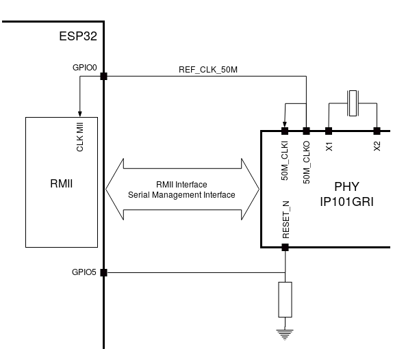
RMII Clock from IP101GRI PHY
Please note that the PHY is reset on power up by pulling the RESET_N signal down with a resistor. ESP32 should assert RESET_N high with GPIO5 to enable PHY. Only this can ensure the power-up of system. Otherwise ESP32 may enter download mode (when the clock signal of REF_CLK_50M is at a high logic level during the GPIO0 power-up sampling phase).
RMII Clock Sourced Internally from ESP32’s APLL
Another option is to source the RMII Clock from internal ESP32 APLL, see figure below. The clock signal coming from GPIO0 is first inverted, to account for transmission line delay, and then supplied to the PHY.
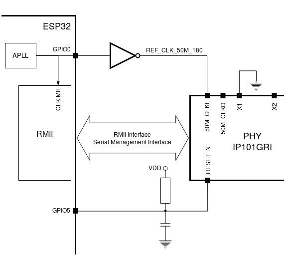
RMII Clock from ESP Internal APLL
To implement this option, users need to remove or add some RC components on the board. For details please refer to the ESP32-Ethernet-Kit V1.2 Ethernet board (A) schematic, sheet 2, location D2. Please note that if the APLL is already used for other purposes (e.g. I2S peripheral), then you have no choice but use an external RMII clock.
Serial Console
UART0 is, by default, the serial console. It connects to the on-board CP2102N bridge and is available on the USB connector.
It will show up as /dev/ttyUSB[n] where [n] will probably be 0.
Ethernet Peripherals
ESP32 has a 802.11 hardware MAC, so just connects to external PHY chip. Due to the limited number of GPIOs in ESP32, it’s recommended to use RMII to connect to an external PHY chip. Current driver also only supports RMII option.
The RMII GPIO pins are fixed, but the SMI and functional GPIO pins are optional.
RMII GPIO pins are as following:
ESP32 GPIO |
PHY Chip GPIO |
|---|---|
IO25 |
RXD[0] |
IO26 |
RXD[1] |
IO27 |
CRS_DV |
IO0 |
REF_CLK |
IO19 |
TXD[0] |
IO21 |
TX_EN |
IO22 |
TXD[1] |
SMI GPIO pins (default option) are as following:
ESP32 GPIO |
PHY Chip GPIO |
|---|---|
IO18 |
MDIO |
IO23 |
MDC |
Functional GPIO pins(default option) are as following:
ESP32 GPIO |
PHY Chip GPIO |
|---|---|
IO5 |
Reset_N |
Pin Mapping
ESP32-WROVER-E |
IP101GRI |
UART |
JTAG |
GPIO |
Comments |
|---|---|---|---|---|---|
S_VP |
IO36 |
||||
S_VN |
IO39 |
||||
IO34 |
IO34 |
||||
IO35 |
IO35 |
||||
IO32 |
IO32 |
||||
IO33 |
IO33 |
||||
IO25 |
RXD[0] |
||||
IO26 |
RXD[1] |
||||
IO27 |
CRS_DV |
||||
IO14 |
TMS |
IO14 |
|||
IO12 |
TDI |
IO12 |
|||
IO13 |
TCK |
IO13 |
|||
IO15 |
TDO |
IO15 |
|||
IO2 |
IO2 |
||||
IO0 |
REF_CLK |
See note 1 |
|||
IO4 |
IO4 |
||||
IO16 |
IO16 (NC) |
See note 2 |
|||
IO17 |
IO17 (NC) |
See note 2 |
|||
IO5 |
Reset_N |
See note 1 |
|||
IO18 |
MDIO |
||||
IO19 |
TXD[0] |
||||
IO21 |
TX_EN |
||||
RXD0 |
RXD |
||||
TXD0 |
TXD |
||||
IO22 |
TXD[1] |
||||
IO23 |
MDC |
Note
1. To prevent the power-on state of the GPIO0 from being affected by the clock output on the PHY side, the RESET_N signal to PHY defaults to low, turning the clock output off. After power-on you can control RESET_N with GPIO5 to turn the clock output on. See also RMII Clock Sourced Externally by PHY. For PHYs that cannot turn off the clock output through RESET_N, it is recommended to use a crystal module that can be disabled/enabled externally. Similarly like when using RESET_N, the oscillator module should be disabled by default and turned on by ESP32 after power-up. For a reference design please see ESP32-Ethernet-Kit V1.2 Ethernet board (A) schematic.
The ESP32 pins GPIO16 and GPIO17 are not broken out to the ESP32-WROVER-E module and therefore not available for use.
Using QEMU:
First follow the instructions at https://github.com/espressif/qemu/wiki to build QEMU.
Enable the
ESP32_QEMU_IMAGEconfig found in “Board Selection -> ESP32 binary image for QEMU”.Download the bootloader and the partition table from https://github.com/espressif/esp-nuttx-bootloader/releases and place them in a directory, say
../esp-bins.Build and generate the QEMU image:
make ESPTOOL_BINDIR=../esp-binsA new image “esp32_qemu_image.bin” will be created. It can be run as:
~/PATH_TO_QEMU/qemu/build/xtensa-softmmu/qemu-system-xtensa -nographic \
   -machine esp32 \
   -drive file=esp32_qemu_image.bin,if=mtd,format=raw
Configurations
All of the configurations presented below can be tested by running the following commands:
$ ./tools/configure.sh esp32-ethernet-kit:<config_name>
$ make flash ESPTOOL_PORT=/dev/ttyUSB0 -j
Where <config_name> is the name of board configuration you want to use, i.e.: nsh, buttons, wifi…
Then use a serial console terminal like picocom configured to 115200 8N1.
autopm
This configuration makes the device automatically enter the low power consumption mode when in the idle state, powering off the cpu and other peripherals.
In minimum power save mode, the station wakes up every DTIM to receive a beacon. The broadcast data will not be lost because it is transmitted after DTIM. However, it can not save much more power if DTIM is short as the DTIM is determined by the access point.
ethernet
This configuration is similar to wifi but uses the Ethernet interface instead
of the WiFi one. It also automatically configures the IP and DNS addresses of the
device. It currently uses the following static configuration:
IP: 192.168.15.100 (0xc0a80f64)
Gateway: 192.168.15.1 (0xc0a80f01)
Netmask: 255.255.255.0 (0xffffff00)
DNS: 8.8.8.8 (0x08080808)
nsh
Basic NuttShell configuration (console enabled in UART0, exposed via USB connection by means of CP2102 converter, at 115200 bps).
oneshot
This config demonstrate the use of oneshot timers present on the ESP32.
To test it, just run the oneshot example:
nsh> oneshot
Opening /dev/oneshot
Maximum delay is 4294967295999999
Starting oneshot timer with delay 2000000 microseconds
Waiting...
Finished
rtc
This configuration demonstrates the use of the RTC driver through alarms. You can set an alarm, check its progress and receive a notification after it expires:
nsh> alarm 10
alarm_daemon started
alarm_daemon: Running
Opening /dev/rtc0
Alarm 0 set in 10 seconds
nsh> alarm -r
Opening /dev/rtc0
Alarm 0 is active with 10 seconds to expiration
nsh> alarm_daemon: alarm 0 received
wifi
Enables Wi-Fi support. You can define your credentials this way:
$ make menuconfig
-> Application Configuration
    -> Network Utilities
        -> Network initialization (NETUTILS_NETINIT [=y])
            -> WAPI Configuration
Or if you don’t want to keep it saved in the firmware you can do it at runtime:
nsh> wapi psk wlan0 mypasswd 3
nsh> wapi essid wlan0 myssid 1
nsh> renew wlan0
Tip
Please refer to ESP32 Wi-Fi Station Mode for more information.