ST Nucleo F746ZG
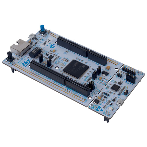
This page discusses issues unique to NuttX configurations for the STMicro Nucleo-144 board. See ST document STM32 Nucleo-144 boards (UM1974):
https://www.st.com/resource/en/user_manual/dm00244518.pdf
Board Features
Peripherals: 8 leds, 2 push button (3 LEDs, 1 button) under software control
Debug: STLINK/V2-1 debugger/programmer Uses a STM32F103CB to provide a ST-Link for programming, debug similar to the OpenOcd FTDI function - USB to JTAG front-end.
Expansion I/F: ST Zio and Extended Arduino and Morpho Headers
ST Nucleo F746ZG board from ST Micro is supported. See
The Nucleo F746ZG order part number is NUCLEO-F746ZG. It is one member of the STM32 Nucleo-144 board family.
NUCLEO-F746ZG Features
Microprocessor: STM32F746ZGT6 Core: ARM 32-bit Cortex®-M7 CPU with FPU, L1-cache: 4KB data cache and 4KB instruction cache, up to 216 MHz, MPU, and DSP instructions.
Memory: 1024 KB Flash 320KB of SRAM (including 64KB of data TCM RAM) + 16KB of instruction TCM RAM + 4KB of backup SRAM
ADC:3×12-bit, 2.4 MSPS ADC: up to 24 channels and 7.2 MSPS in triple interleaved mode
DMA: 2 X 16-stream DMA controllers with FIFOs and burst support
Timers: Up to 18 timers: up to thirteen 16-bit (1x 16-bit low power), two 32-bit timers, 2x watchdogs, SysTick
GPIO: 114 I/O ports with interrupt capability
LCD: LCD-TFT Controller with (DMA2D), Parallel interface
I2C: 4 × I2C interfaces (SMBus/PMBus)
U[S]ARTs: 4 USARTs, 4 UARTs (27 Mbit/s, ISO7816 interface, LIN, IrDA, modem control)
SPI/12Ss: 6/3 (simplex) (up to 50 Mbit/s), 3 with muxed simplex I2S for audio class accuracy via internal audio PLL or external clock
QSPI: Dual mode Quad-SPI
SAIs: 2 Serial Audio Interfaces
CAN: 2 X CAN interface
SDMMC interface
SPDIFRX interface
USB: USB 2.0 full-speed device/host/OTG controller with on-chip PHY
10/100 Ethernet: MAC with dedicated DMA: supports IEEE 1588v2 hardware, MII/RMII
Camera Interface: 8/14 Bit
CRC calculation unit
TRG: True random number generator
RTC
See https://developer.mbed.org/platforms/ST-Nucleo-F746ZG for additional information about this board.
Hardware
GPIO - there are 144 I/O lines on the STM32F7xxZxT6 with various pins pined out on the Nucleo 144.
See https://developer.mbed.org/platforms/ST-Nucleo-F746ZG/ for slick graphic pinouts.
Keep in mind that:
The I/O is 3.3 Volt not 5 Volt like on the Arduino products.
The Nucleo-144 board family has 3 pages of Solder Bridges AKA Solder Blobs (SB) that can alter the factory configuration. We will note SB in effect but will assume the factory default settings.
Our main concern is establishing a console and LED utilization for debugging. Because so many pins can be multiplexed with so many functions, the above mentioned graphic may be helpful in identifying a serial port.
There are 5 choices that can be made from the menuconfig:
CONFIG_NUCLEO_CONSOLE_ARDUINO or CONFIG_NUCLEO_CONSOLE_MORPHO or
CONFIG_NUCLEO_CONSOLE_MORPHO_UART4 or CONFIG_NUCLEO_CONSOLE_VIRTUAL or
CONFIG_NUCLEO_CONSOLE_NONE
The CONFIG_NUCLEO_CONSOLE_NONE makes no preset for the console. You should still visit the U[S]ART selection and Device Drivers to disable any U[S]ART remaining.
The CONFIG_NUCLEO_CONSOLE_ARDUINO configurations assume that you are using a standard Arduino RS-232 shield with the serial interface with RX on pin D0 and TX on pin D1 from USART6:
-------- ---------------
            STM32F7
ARDUIONO FUNCTION  GPIO
-- ----- --------- -----
DO RX    USART6_RX PG9
D1 TX    USART6_TX PG14
-- ----- --------- -----
The CONFIG_NUCLEO_CONSOLE_MORPHO configurations uses Serial Port 8 (USART8) with TX on PE1 and RX on PE0.:
Serial
------
SERIAL_RX         PE_0
SERIAL_TX         PE_1
The CONFIG_NUCLEO_CONSOLE_MORPHO_UART4 configurations uses Serial Port 4 (UART4) with TX on PA1 and RX on PA0. Zero Ohm resistor / solder short at SB13 must be removed/open. (Disables Ethernet MII clocking.):
Serial
------
SERIAL_RX         PA_1  CN11 30
SERIAL_TX         PA_0  CN11 28
The CONFIG_NUCLEO_CONSOLE_VIRTUAL configurations uses Serial Port 3 (USART3) with TX on PD8 and RX on PD9.:
Serial
------
SERIAL_RX         PD9
SERIAL_TX         PD8
These signals are internally connected to the on board ST-Link.
Of course if your design has used those pins you can choose a completely different U[S]ART to use as the console. In that Case, you will need to edit the include/board.h to select different U[S]ART and / or pin selections.
LEDs
The Board provides a 3 user LEDs, LD1-LD3:
LED1 (Green)      PB_0  (SB120 ON and SB119 OFF)
LED2 (Blue)       PB_7  (SB139 ON)
LED3 (Red)        PB_14 (SP118 ON)
When the I/O is HIGH value, the LEDs are on.
When the I/O is LOW, the LEDs are off.
These LEDs are not used by the board port unless CONFIG_ARCH_LEDS is defined. In that case, the usage by the board port is defined in include/board.h and src/stm32_autoleds.c. The LEDs are used to encode OS related events as follows when the LEDs are available:
SYMBOL
Meaning
RED
GREEN
BLUE
LED_STARTED
NuttX has been started
OFF
OFF
OFF
LED_HEAPALLOCATE
Heap has been allocated
OFF
OFF
ON
LED_IRQSENABLED
Interrupts enabled
OFF
ON
OFF
LED_STACKCREATED
Idle stack created
OFF
ON
ON
LED_INIRQ
In an interrupt
NC
NC
ON (momentary)
LED_SIGNAL
In a signal handler
NC
ON
OFF (momentary)
LED_ASSERTION
An assertion failed
ON
NC
ON (momentary)
LED_PANIC
The system has crashed
ON
OFF
OFF (flashing 2Hz)
LED_IDLE
MCU is is sleep mode
ON
OFF
OFF
- OFF - means that the OS is still initializing. Initialization is very fast
so if you see this at all, it probably means that the system is hanging up somewhere in the initialization phases.
GREEN - This means that the OS completed initialization.
- BLUE - Whenever and interrupt or signal handler is entered, the BLUE LED is
illuminated and extinguished when the interrupt or signal handler exits.
- VIOLET - If a recovered assertion occurs, the RED and blue LED will be
illuminated briefly while the assertion is handled. You will probably never see this.
- Flashing RED - In the event of a fatal crash, all other LEDs will be
extinguished and RED LED will FLASH at a 2Hz rate.
Thus if the GREEN LED is lit, NuttX has successfully booted and is, apparently, running normally. If the RED LED is flashing at approximately 2Hz, then a fatal error has been detected and the system has halted.
Serial Consoles
USART6 (CONFIG_NUCLEO_CONSOLE_ARDUINO)
ARDUINO
FUNCTION
GPIO
DO RX
USART6_RX
PG9
D1 TX
USART6_TX
PG14
You must use a 3.3 TTL to RS-232 converter or a USB to 3.3V TTL
Nucleo 144           FTDI TTL-232R-3V3
-------------       -------------------
TXD - D1-TXD   -    RXD - Pin 5 (Yellow)
RXD - D0-RXD   -    TXD - Pin 4 (Orange)
GND   GND      -    GND   Pin 1  (Black)
-------------       -------------------

*Note you will be reverse RX/TX
Use make menuconfig to configure USART6 as the console:
CONFIG_STM32_USART6=y
CONFIG_USARTs_SERIALDRIVER=y
CONFIG_USARTS_SERIAL_CONSOLE=y
CONFIG_USART6_RXBUFSIZE=256
CONFIG_USART6_TXBUFSIZE=256
CONFIG_USART6_BAUD=115200
CONFIG_USART6_BITS=8
CONFIG_USART6_PARITY=0
CONFIG_USART6_2STOP=0
USART8 (CONFIG_NUCLEO_CONSOLE_MORPHO)
Pins and Connectors:
FUNC GPIO  Connector
               Pin NAME
---- ---   ------- ----
TXD: PE1   CN11-61, PE1
RXD: PE0   CN12-64, PE0
           CN10-33, D34
---- ---   ------- ----
You must use a 3.3 TTL to RS-232 converter or a USB to 3.3V TTL:
Nucleo 144           FTDI TTL-232R-3V3
-------------       -------------------
TXD - CN11-61   -   RXD - Pin 5 (Yellow)
RXD - CN12-64   -   TXD - Pin 4 (Orange)
GND   CN12-63   -   GND   Pin 1  (Black)
-------------       -------------------

*Note you will be reverse RX/TX
Use make menuconfig to configure USART8 as the console:
CONFIG_STM32_UART8=y
CONFIG_UART8_SERIALDRIVER=y
CONFIG_UART8_SERIAL_CONSOLE=y
CONFIG_UART8_RXBUFSIZE=256
CONFIG_UART8_TXBUFSIZE=256
CONFIG_UART8_BAUD=115200
CONFIG_UART8_BITS=8
CONFIG_UART8_PARITY=0
CONFIG_UART8_2STOP=0
Virtual COM Port (CONFIG_NUCLEO_CONSOLE_VIRTUAL)
Yet another option is to use USART3 and the USB virtual COM port. This option may be more convenient for long term development, but is painful to use during board bring-up.
Solder Bridges. This configuration requires:
PD8 USART3 TX SB5 ON and SB7 OFF (Default)
PD9 USART3 RX SB6 ON and SB4 OFF (Default)
Configuring USART3 is the same as given above but add the S and #3.
Question: What BAUD should be configure to interface with the Virtual COM port? 115200 8N1?
Default:
As shipped, SB4 and SB7 are open and SB5 and SB6 closed, so the virtual COM port is enabled.
SPI
Since this board is so generic, having a quick way to set the SPI configuration seams in order. So the board provides a quick test that can be selected vi CONFIG_NUCLEO_SPI_TEST that will initialize the selected buses (SPI1-SPI3) and send some text on the bus at application initialization time.
SDIO
To test the SD performance one can use a SparkFun microSD Sniffer from https://www.sparkfun.com/products/9419 or similar board and connect it as follows:
VCC    V3.3 CN11  16
GND    GND  CN11-8
CMD    PD2  CN11-4
CLK    PC12 CN11-3
DAT0 - PC8  CN12-2
DAT1 - PC9  CN12-1
DAT2   PC10 CN11-1
CD     PC11 CN11-2
LoRa Concentrator Shield
The board supports a LoRa gateway shield of the LRWAN_GS_HF1 family, such as the RisingHF RHF0M301, which carries a Semtech SX1301 baseband processor and two SX1257 radio front ends. The shield is wired to SPI4 on the morpho connector:
FUNCTION      GPIO  CONNECTOR
------------  ----  ---------
SPI4_SCK      PE12  CN11-49
SPI4_MISO     PE13  CN11-47
SPI4_MOSI     PE14  CN11-45
SPI4_CS       PE11  CN11-53
SX1301_RESET  PE15  active high
BAND_SET1     PD15  D9,  front end filter select
BAND_SET2     PE9   D6,  front end filter select
------------  ----  ---------
The chip select is driven as a plain output rather than by the hardware NSS, as the concentrator needs it held low for a whole burst. The two band selection lines drive the filter bank of the shield: 915 MHz uses SET1 low and SET2 high, 868 MHz the other way around.
With CONFIG_LPWAN_SX1301 selected, the board registers the concentrator
at /dev/lora0, behind the device independent gateway interface. That
interface, the configuration options of the driver and the channel plans it
supports are documented in LoRa gateway (concentrator) API.
The same shields usually carry a serial NOR flash on SPI5 (PF7 SCK, PF8
MISO, PF9 MOSI, PF6 CS). The pins are defined in include/board.h and the
chip select is handled by the board, but no MTD driver is registered for it
yet.
Configurations
nsh
Configures the NuttShell (nsh) located at apps/examples/nsh for the Nucleo-144 boards. The Configuration enables the serial interfaces on USART6. Support for builtin applications is enabled, but in the base configuration no builtin applications are selected (see NOTES below).
NOTES:
This configuration uses the mconf-based configuration tool. To change this configuration using that tool, you should:
Build and install the kconfig-mconf tool. See nuttx/README.txt see additional README.txt files in the NuttX tools repository.
If this is the initial configuration then execute:
./tools/configure.sh nucleo-f746zg:nsh
in nuttx/ in order to start configuration process. Caution: Doing this step more than once will overwrite .config with the contents of the nucleo-f746zg/nsh/defconfig file.
Execute ‘make oldconfig’ in nuttx/ in order to refresh the configuration.
Execute ‘make menuconfig’ in nuttx/ in order to start the reconfiguration process.
Save the .config file to reuse it in the future starting at step d.
By default, this configuration uses the ARM GNU toolchain for Linux. That can easily be reconfigured, of course.:
CONFIG_HOST_LINUX=y                     : Builds under Linux
CONFIG_ARM_TOOLCHAIN_GNU_EABI=y      : ARM GNU for Linux
- The serial console may be configured to use either USART3 (which would
correspond to the Virtual COM port) or with the console device configured for USART6 to support an Arduino serial shield (see instructions above under “Serial Consoles). You will need to check the defconfig file to see how the console is set up and, perhaps, modify the configuration accordingly.
To select the Virtual COM port:
-CONFIG_NUCLEO_CONSOLE_ARDUINO
+CONFIG_NUCLEO_CONSOLE_VIRTUAL=y
-CONFIG_USART6_SERIAL_CONSOLE=y
+CONFIG_USART3_SERIAL_CONSOLE=y
To select the Arduino serial shield:
-CONFIG_NUCLEO_CONSOLE_VIRTUAL=y
+CONFIG_NUCLEO_CONSOLE_ARDUINO
-CONFIG_USART3_SERIAL_CONSOLE=y
+CONFIG_USART6_SERIAL_CONSOLE=y
Default values for other settings associated with the select USART should be correct.
evalos:
This configuration is designed to test the features of the board.
Configures the NuttShell (nsh) located at apps/examples/nsh for the Nucleo-144 boards. The console is available on serial interface USART3, which is accessible over the USB ST-Link interface.
Configures nsh with advanced features such as autocompletion.
Configures the on-board LEDs to work with the ‘leds’ example app.
Configures the 'helloxx' example app.
Adds character device for i2c1
Tries to register mpu60x0 IMU to i2c1
NOTES:
This configuration uses the mconf-based configuration tool. To change this configuration using that tool, you should:
Build and install the kconfig-mconf tool. See nuttx/README.txt see additional README.txt files in the NuttX tools repository.
If this is the initial configuration then execute:
./tools/configure.sh nucleo-144:evalos
in nuttx/ in order to start configuration process. Caution: Doing this step more than once will overwrite .config with the contents of the nucleo-f746zg/evalos/defconfig file.
Execute ‘make oldconfig’ in nuttx/ in order to refresh the configuration.
Execute ‘make menuconfig’ in nuttx/ in order to start the reconfiguration process.
Save the .config file to reuse it in the future starting at step d.
By default, this configuration uses the ARM GNU toolchain for Linux. That can easily be reconfigured, of course.:
CONFIG_HOST_LINUX=y                     : Builds under Linux
CONFIG_ARM_TOOLCHAIN_GNU_EABI=y      : ARM GNU for Linux
lorawan_gw
Turns the board into a LoRaWAN gateway: the SX1301 concentrator on SPI4 and the Ethernet interface with DHCP and DNS. The console is the virtual COM port on USART3.
Selecting CONFIG_WIRELESS_LORA_PKT_FWD adds the Semtech UDP packet
forwarder of apps/wireless/lora_pkt_fwd, which is what turns the
concentrator into a gateway and provides the lora command used below.
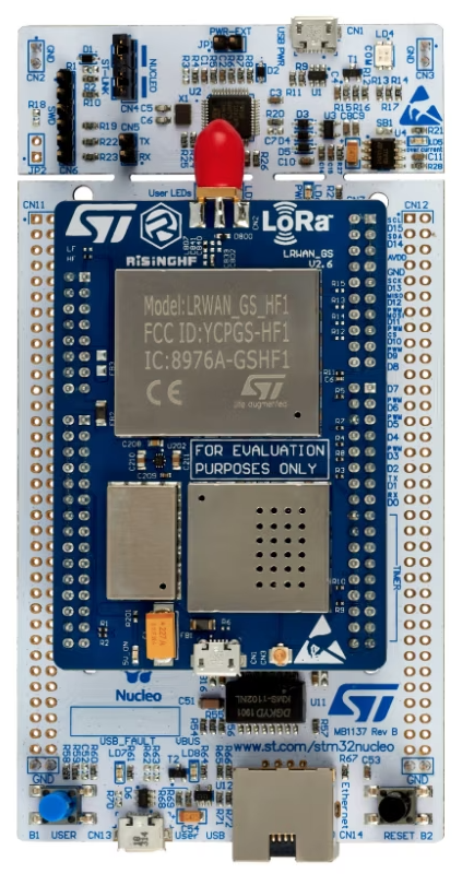
The board with an LRWAN_GS_HF1 shield mounted on the morpho headers.
Build and flash:
$ ./tools/configure.sh nucleo-f746zg:lorawan_gw
$ make
$ cp nuttx.bin /media/<user>/NODE_F746ZG/
The forwarder and the concentrator are driven by the lora command, which
mirrors the AT command set of the vendor gateway firmwares:
nsh> lora                        # list the subcommands
nsh> lora sys                    # identity, network and channel plan
nsh> lora ch                     # show the channel plan
nsh> lora ch EU868               # change region: AU915, AU915-1, US915,
                                 # US915-1, EU868, AS923, KR920, IN866
nsh> lora server <host> [up] [down]   # network server, name or address
nsh> lora start                  # start the concentrator and forward
nsh> lora status                 # counters of both sides
nsh> lora stop
nsh> lora tx 917200000 7 hello   # transmit one packet, for bring-up
The last one exists to bring a gateway up without a network server: it sends a single packet with the polarity of an uplink, so any LoRa receiver tuned to the same frequency, spreading factor and 125 kHz bandwidth sees it.
The default region is the second sub-band of AU915 (channels 8 to 15 plus the
500 kHz channel 65), which is what The Things Network and the Brazilian
deployments use; AU915-1 selects the first sub-band instead. The default
server and the gateway identifier come from the configuration
(CONFIG_LORA_PKT_FWD_SERVER and CONFIG_LORA_PKT_FWD_EUI) and both can
be changed at runtime.
A working session looks like this:
nsh> lora start
sx1301_reg_probe: SX1301 detected, version 0x67
sx1301_setup_radio: Radio A: PLL locked at 917100000 Hz
sx1301_setup_radio: Radio B: PLL locked at 917900000 Hz
sx1301_calibrate: Calibration done, status 0xbf
sx1301_agc_start: AGC running, radio map 0xf0
sx1301_start: Concentrator started, modems 0x0b
lora: forwarding to au1.cloud.thethings.network (up 1700, down 1700)
sx1301_receive: RX chain 0 SF10 915200000 Hz snr 14.0 dB size 23 status 0x10
lora: forwarded 1 packet(s)
Note that the sync word has to match the devices: the driver configures the
concentrator for a public LoRaWAN network, and
CONFIG_LPWAN_SX1301_PRIVATE_NETWORK switches it to a private one.