i.MX RT1180 EVK
The i.MX RT1180 EVK is an evaluation kit from NXP. It is based on the MIMXRT1189 crossover microcontroller, which combines Arm Cortex-M33 and Cortex-M7 cores. See the MIMXRT1180-EVK Quick Start Guide for an overview of the board and its connectors.
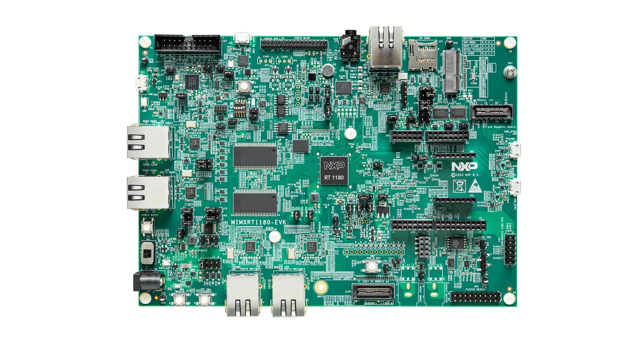
i.MX RT1180 EVK top view. Image source: NXP.
Features
- MIMXRT1189CVM8C microcontroller
Cortex-M33 running at 266 MHz with NuttX
Cortex-M7 running at 798 MHz with NuttX
- Memory
On-chip TCM and OCRAM
512-Mbit external SDRAM
128-Mbit FlexSPI1 QSPI NOR flash
512-Mbit HyperRAM
MicroSD card socket
- Connectivity and expansion
MCU-Link debug interface with a virtual COM port
20-pin external JTAG/SWD connector
Ethernet connectors
USB host and device connectors
CAN connector
Arduino-compatible expansion headers
Audio codec, microphone, headphone jack, and speaker connections
Two software-controlled user LEDs
The current NuttX configurations provide the serial console, USB device
support, image generation, and multicore boot flow. The Cortex-M7 nsh
configuration also enables the onboard MicroSD socket through USDHC1. Other
on-board interfaces listed above are not enabled by the supplied
configurations.
Serial Console
The default serial console is LPUART1 through the MCU-Link virtual COM port:
Function |
Signal |
Pad |
|---|---|---|
Console TX |
LPUART1_TX |
GPIO_AON_08 |
Console RX |
LPUART1_RX |
GPIO_AON_09 |
Connect the host to the MCU-Link USB connector J53. On Linux, the console is
normally available as /dev/ttyACM0.
Pin Mapping
The board port currently defines these on-board connections:
Pad |
Function |
Board connection |
|---|---|---|
GPIO_AON_04 |
LPSPI1_SCK |
On-board LPSPI NOR flash |
GPIO_AON_05 |
LPSPI1_PCS0 |
On-board LPSPI NOR flash |
GPIO_AON_06 |
LPSPI1_SDO |
On-board LPSPI NOR flash |
GPIO_AON_07 |
LPSPI1_SDI |
On-board LPSPI NOR flash |
GPIO_AON_08 |
LPUART1_TX |
MCU-Link virtual COM port |
GPIO_AON_09 |
LPUART1_RX |
MCU-Link virtual COM port |
GPIO_AON_15 |
LPI2C2_SDA |
On-board peripherals |
GPIO_AON_16 |
LPI2C2_SCL |
On-board peripherals |
GPIO_AD_26 |
GPIO4_IO26 |
Red user LED D7 |
GPIO_AD_27 |
GPIO4_IO27 |
Green user LED D6 |
Consult the MIMXRT1180-EVK user manual (UM12021) and schematic, available from the NXP product page linked above, for the complete expansion-header pinout and any signal-sharing restrictions.
Power Supply
The board requires a 5 V supply. It can be powered from the external 5 V input J2, or from a supported USB connector when the power-selection jumpers are configured accordingly. Use SW1 to turn the board on. Refer to the board user manual before changing the factory jumper settings or powering the board from more than one source.
Installation
All testing has been conducted using the following Arm GNU Toolchain for the
arm-none-eabi target, available from the Arm GNU Toolchain downloads page:
$ arm-none-eabi-gcc --version
arm-none-eabi-gcc (Arm GNU Toolchain 13.2.rel1 (Build arm-13.7)) 13.2.1 20231009
Building a Cortex-M33 image also requires python3 with the venv
module, pip, and either curl or wget. The image-building helper
creates a private Python environment and installs the pinned NXP SPSDK
version automatically.
Flashing requires the SEGGER J-Link Software and Documentation Pack version 7.98a or later, one of:
a SEGGER J-Link probe connected to the 20-pin JTAG/SWD connector J37; or
the on-board MCU-Link probe, reflashed with SEGGER MCU-Link J-Link firmware and connected through J53,
and the boot-mode DIP switch SW5 set to 0100 (FlexSPI Quad SPI NOR boot).
Building NuttX
Select a configuration and build it from the NuttX repository root:
$ ./tools/configure.sh imxrt1180-evk:<config>
$ make -j$(nproc)
The first Cortex-M33 build downloads the pinned NXP EdgeLock Enclave (ELE)
firmware after displaying its license and installs SPSDK into
tools/imxrt1180/.cache. Running the build implies acceptance of the NXP
firmware license described in License Exceptions.
Flash Layout
The Cortex-M33 image is the bootable image. It contains the FlexSPI
Configuration Block (FCB) at offset 0x400 and the AHAB container at offset
0x1000. The Cortex-M7 image is programmed separately as a raw XIP payload.
Address |
Offset |
Size |
Contents |
|---|---|---|---|
0x28000000 |
0x0 |
512 KB |
Cortex-M33 image, |
0x28080000 |
0x80000 |
Rest |
Cortex-M7 image, |
Flashing
Set the boot-mode DIP switch SW5 to 0100 for FlexSPI Quad SPI NOR boot.
The flash-jlink.sh helper takes an image name and either a flash offset or
an absolute address.
The helper programs through the Cortex-M33 device profile because the RT1180 ROM starts the Cortex-M33 first and initializes FlexSPI1 before the SEGGER flash loader runs. Always use the supplied helper for programming. The Cortex-M7 J-Link device profile is intended for debugging the running Cortex-M7 image, not for programming.
To flash a standalone Cortex-M33 NSH image:
$ ./tools/configure.sh imxrt1180-evk:nsh-m33
$ make -j$(nproc)
$ boards/arm/imxrt/imxrt1180-evk/tools/flash-jlink.sh flash.bin 0x0
To flash the Cortex-M33 bootloader and Cortex-M7 NSH images:
$ ./tools/configure.sh imxrt1180-evk:bl
$ make -j$(nproc)
$ cp flash.bin flash-bl.bin
$ make distclean
$ ./tools/configure.sh imxrt1180-evk:nsh
$ make -j$(nproc)
$ cp nuttx.bin nuttx-m7.bin
$ boards/arm/imxrt/imxrt1180-evk/tools/flash-jlink.sh flash-bl.bin 0x0
$ boards/arm/imxrt/imxrt1180-evk/tools/flash-jlink.sh nuttx-m7.bin 0x80000
J-Link Debugging
The board port also supplies a J-Link GDB server helper for Cortex-M7:
$ boards/arm/imxrt/imxrt1180-evk/tools/gdbserver-jlink.sh
Connect from another terminal:
$ arm-none-eabi-gdb nuttx
(gdb) target extended-remote localhost:2331
(gdb) monitor reset
(gdb) continue
Configurations
The board identifier for use with tools/configure.sh is
imxrt1180-evk.
nsh-m33
Runs NuttShell (NSH) directly on the Cortex-M33. The RT1180 ROM boots
flash.bin from FlexSPI1 QSPI NOR. NSH is available on LPUART1 at
the MCU-Link virtual COM port. This configuration also enables USB CDC/ACM
and the ostest application.
bl
Builds a minimal Cortex-M33 bootloader as flash.bin. It sets the
Cortex-M7 boot address to 0x28080000, releases that core, and then remains
in an indefinite loop that periodically calls usleep. Use this
configuration together with nsh; it does not provide an interactive shell
itself.
nsh
Runs NSH on the Cortex-M7. The output nuttx.bin is a raw XIP payload that
must be programmed at offset 0x80000 and started by the bl
configuration. NSH is available on LPUART1 at the MCU-Link virtual COM port.
This configuration also enables USB CDC/ACM, the ostest application, and
the onboard MicroSD socket via USDHC1.
License Exceptions
The Cortex-M33 image build downloads
mxrt1180b0-ahab-container.img from NXP’s MCUXpresso SDK at a pinned commit.
This proprietary EdgeLock Enclave firmware is covered by the LA_OPT NXP
Software License, version 56 (April 2024). The download helper displays the
source URL, license URL, and expected SHA-256 digest before downloading it.
The NXP SPSDK Python package used to assemble the boot image is distributed under the BSD-3-Clause license.