ESP32-C6-DevKitM-1
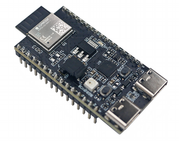
ESP32-C6-DevKitM-1 is an entry-level development board based on ESP32-C6-MINI-1(U), a general-purpose module with a 4 MB SPI flash. This board integrates complete Wi-Fi, Bluetooth LE, Zigbee, and Thread functions. You can find the board schematic here.
Most of the I/O pins are broken out to the pin headers on both sides for easy interfacing. Developers can either connect peripherals with jumper wires or mount ESP32-C6-DevKitM-1 on a breadboard.

ESP32-C6-DevKitM-1 Board Layout
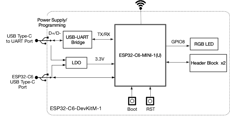
The block diagram below presents main components of the ESP32-C6-DevKitM-1.

ESP32-C6-DevKitM-1 Electrical Block Diagram
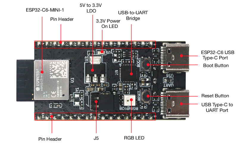
Hardware Components

ESP32-C6-DevKitM-1 Hardware Components
Board LEDs
There is one on-board LED that indicates the presence of power. Another WS2812 LED is connected to GPIO8 and is available for software.
Current Measurement
The J5 headers on the ESP32-C6-DevKitM-1 can be used for measuring the current drawn by the ESP32-C6-MINI-1(U) module:
Remove the jumper: Power supply between the module and peripherals on the board is cut off. To measure the module’s current, connect the board with an ammeter via J5 headers;
Apply the jumper (factory default): Restore the board’s normal functionality.
Note
When using 3V3 and GND pin headers to power the board, please remove the J5 jumper, and connect an ammeter in series to the external circuit to measure the module’s current.
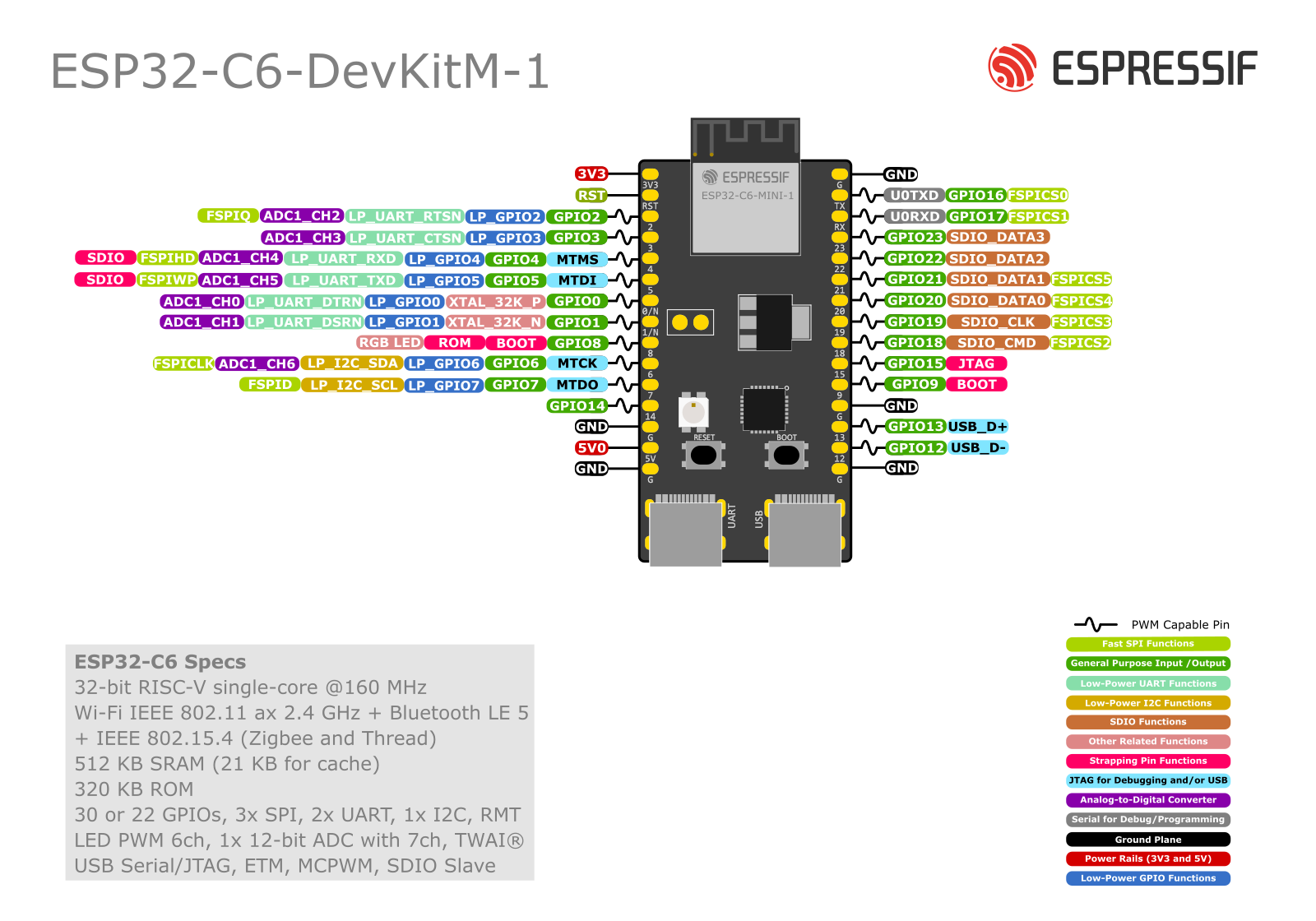
Pin Mapping

ESP32-C6-DevKitM-1 Pin Layout
Configurations
All of the configurations presented below can be tested by running the following commands:
$ ./tools/configure.sh esp32c6-devkitm:<config_name>
$ make flash ESPTOOL_PORT=/dev/ttyUSB0 -j
Where <config_name> is the name of board configuration you want to use, i.e.: nsh, buttons, wifi…
Then use a serial console terminal like picocom configured to 115200 8N1.
coremark
This configuration sets the CoreMark benchmark up for running on the maximum number of cores for this system. It also enables some optimization flags and disables the NuttShell to get the best possible score.
Note
As the NSH is disabled, the application will start as soon as the system is turned on.
gpio
This is a test for the GPIO driver. It uses GPIO1 and GPIO2 as outputs and GPIO9 as an interrupt pin.
At the nsh, we can turn the outputs on and off with the following:
nsh> gpio -o 1 /dev/gpio0
nsh> gpio -o 1 /dev/gpio1

nsh> gpio -o 0 /dev/gpio0
nsh> gpio -o 0 /dev/gpio1
We can use the interrupt pin to send a signal when the interrupt fires:
nsh> gpio -w 14 /dev/gpio2
The pin is configured as a rising edge interrupt, so after issuing the above command, connect it to 3.3V.
nsh
Basic configuration to run the NuttShell (nsh).
ostest
This is the NuttX test at apps/testing/ostest that is run against all new
architecture ports to assure a correct implementation of the OS.
pwm
This configuration demonstrates the use of PWM through a LED connected to GPIO8.
To test it, just execute the pwm application:
nsh> pwm
pwm_main: starting output with frequency: 10000 duty: 00008000
pwm_main: stopping output
rmt
This configuration configures the transmitter and the receiver of the
Remote Control Transceiver (RMT) peripheral on the ESP32-C6 using GPIOs 8
and 2, respectively. The RMT peripheral is better explained
here,
in the ESP-IDF documentation. The minimal data unit in the frame is called the
RMT symbol, which is represented by rmt_item32_t in the driver:

The example rmtchar can be used to test the RMT peripheral. Connecting
these pins externally to each other will make the transmitter send RMT items
and demonstrates the usage of the RMT peripheral:
nsh> rmtchar
WS2812 addressable RGB LEDs
This same configuration enables the usage of the RMT peripheral and the example
ws2812 to drive addressable RGB LEDs:
nsh> ws2812
Please note that this board contains an on-board WS2812 LED connected to GPIO8 and, by default, this config configures the RMT transmitter in the same pin.
rtc
This configuration demonstrates the use of the RTC driver through alarms. You can set an alarm, check its progress and receive a notification after it expires:
nsh> alarm 10
alarm_daemon started
alarm_daemon: Running
Opening /dev/rtc0
Alarm 0 set in 10 seconds
nsh> alarm -r
Opening /dev/rtc0
Alarm 0 is active with 10 seconds to expiration
nsh> alarm_daemon: alarm 0 received
spiflash
This config tests the external SPI that comes with the ESP32-C6 module connected through SPI1.
By default a SmartFS file system is selected. Once booted you can use the following commands to mount the file system:
nsh> mksmartfs /dev/smart0
nsh> mount -t smartfs /dev/smart0 /mnt
timer
This config test the general use purpose timers. It includes the 4 timers, adds driver support, registers the timers as devices and includes the timer example.
To test it, just run the following:
nsh> timer -d /dev/timerx
Where x in the timer instance.
usbconsole
This configuration tests the built-in USB-to-serial converter found in ESP32-C6.
esptool can be used to check the version of the chip and if this feature is
supported. Running esptool.py -p <port> chip_id should have Chip is
ESP32-C6 in its output.
When connecting the board a new device should appear, a /dev/ttyACMX on Linux
or a /dev/cu.usbmodemXXX om macOS.
This can be used to flash and monitor the device with the usual commands:
make download ESPTOOL_PORT=/dev/ttyACM0
minicom -D /dev/ttyACM0
watchdog
This configuration tests the watchdog timers. It includes the 1 MWDTS, adds driver support, registers the WDTs as devices and includes the watchdog example application.
To test it, just run the following command:
nsh> wdog -i /dev/watchdogX
Where X is the watchdog instance.