ESP32 DevKitC
The ESP32 DevKitC is a development board for the ESP32 SoC from Espressif, based on a ESP-WROOM-32 module. You can find the original V2 version and the newer V4 variant. They are pin compatible.
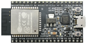
ESP32 DevKitC/Core V2 |
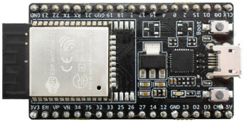
ESP32 DevKitC V4 |
Features
ESP32 WROOM Module
USB-to-UART bridge via micro USB port
Power LED
EN and BOOT buttons (BOOT accessible to user)
SPI FLASH (size varies according to model
Serial Console
UART0 is, by default, the serial console. It connects to the on-board CP2102 converter and is available on the USB connector USB CON8 (J1).
It will show up as /dev/ttypUSB[n] where [n] will probably be 0 (is it 1 on my PC because I have a another device at ttyUSB0).
Ethernet
ESP32 has a 802.11 hardware MAC, so just connects to external PHY chip. Due to the limited number of GPIOs in ESP32, it’s recommended to use RMII to connect to an external PHY chip. Current driver also only supports RMII option.
The RMII GPIO pins are fixed, but the SMI and functional GPIO pins are optional.
RMII GPIO pins are as following:
ESP32 GPIO |
PHY Chip GPIO |
|---|---|
IO25 |
RXD[0] |
IO26 |
RXD[1] |
IO27 |
CRS_DV |
IO0 |
REF_CLK |
IO19 |
TXD[0] |
IO21 |
TX_EN |
IO22 |
TXD[1] |
SMI GPIO pins (default option) are as following:
ESP32 GPIO |
PHY Chip GPIO |
|---|---|
IO18 |
MDIO |
IO23 |
MDC |
Functional GPIO pins(default option) are as following:
ESP32 GPIO |
PHY Chip GPIO |
|---|---|
IO5 |
Reset_N |
Espressif has an official Ethernet development board.
This driver has been tested according to this board and ESP32 core board + LAN8720 module. If users have some issue about using this driver, please refer the upper official document, specially the issue that GPIO0 causes failing to bring the ESP32 chip up.
I2S
ESP32 has two I2S peripherals accessible using either the generic I2S audio driver or a specific audio codec driver (CS4344 bindings are available at the moment). The generic I2S audio driver enables using both the receiver module (RX) and the transmitter module (TX) without using any specific codec. Also, it’s possible to use the I2S character device driver to bypass the audio subsystem and write directly to the I2S peripheral.
Note
The I2S peripheral is able to work on two functional modes internally: 16 and 32-bit width. ESP32’s I2S driver, however, uses an internal buffer to enable inserting padding bytes and provide the ability to play 8, 16, 24 or 32-bits/sample audio files. Sample rate and data width are automatically set by the upper half audio driver.
Note
Also, it’s possible to use 8, 16, 24, and 32-bit-widths writing directly to the I2S character device. Just make sure to set the bit-width:
$ make menuconfig
-> System Type
    -> ESP32 Peripheral Selection
        -> I2S
            -> I2S0/1
                -> Bit Witdh
And make sure the data stream buffer being written to the I2S peripheral is aligned to the next boundary i.e. 16 bits for the 8 and 16-bit-widths and 32 bits for 24 and 32-bit-widths.
Pin Mapping
Todo
To be updated
Pin |
Signal |
Notes |
|---|---|---|
? |
? |
? |
Configurations
audio
This configuration uses the I2S0 peripheral and an externally connected audio codec to play an audio file streamed over an HTTP connection while connected to a Wi-Fi network.
Audio Codec Setup
The CS4344 audio codec is connected on the following pins:
ESP32 Pin |
CS4344 Pin |
Description |
|---|---|---|
0 |
MCLK |
Master Clock |
4 |
SCLK |
Serial Clock |
5 |
LRCK |
Left Right Clock (Word Select) |
18 |
SDIN |
Serial Data In on CS4344. (DOUT on ESP32) |
Simple HTTP server
Prepare a PCM-encoded (.wav) audio file with 16 or 24 bits/sample (sampled at 16~48kHz). This file must be placed into a folder in a computer that could be accessed on the same Wi-Fi network the ESP32 will be connecting to.
Python provides a simple HTTP server. cd to the audio file folder on the PC and run:
$ python3 -m http.server

Serving HTTP on 0.0.0.0 port 8000 (http://0.0.0.0:8000/)
Look for your PC IP address and test playing the prepared audio on your browser:
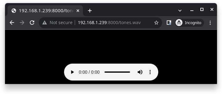
After successfully built and flashed, connect the board to the Wi-Fi network:
nsh> wapi psk wlan0 mypasswd 1
nsh> wapi essid wlan0 myssid 1
nsh> renew wlan0
Once connected, open NuttX’s player and play the file according to its file name and the IP address of the HTTP server:
nsh> nxplayer
nxplayer> play http://192.168.1.239:8000/tones.wav
efuse
A config with EFUSE enabled.
i2schar
This configuration enables the I2S character device and the i2schar example app, which provides an easy-to-use way of testing the I2S peripherals (I2S0 and I2S1), enabling both the TX and the RX for those peripherals.
I2S0 pinout
ESP32 Pin |
Signal Pin |
Description |
|---|---|---|
0 |
MCLK |
Master Clock |
4 |
BCLK |
Bit Clock (SCLK) |
5 |
WS |
Word Select (LRCLK) |
18 |
DOUT |
Data Out |
19 |
DIN |
Data IN |
I2S1 pinout
ESP32 Pin |
Signal Pin |
Description |
|---|---|---|
22 |
BCLK |
Bit Clock (SCLK) |
23 |
WS |
Word Select (LRCLK) |
25 |
DOUT |
Data Out |
26 |
DIN |
Data IN |
After successfully built and flashed, run on the boards’s terminal:
i2schar -p /dev/i2schar[0-1]
The corresponding output should show related debug informations.
knsh
This is identical to the nsh configuration except that (1) NuttX is built as PROTECTED mode, monolithic module and the user applications are built separately and, as a consequence, (2) some features that are only available in the FLAT build are disabled.
Protected Mode support for ESP32 relies on the PID Controller peripheral for implementing isolation between Kernel and Userspace.
By working together with the MMU and Static MPUs of the ESP32, the PID Controller is able to restrict the application access to peripherals, on-chip memories (Internal ROM and Internal SRAM) and off-chip memories (External Flash and PSRAM).
Warning
The PID Controller driver is in EXPERIMENTAL state, so please consider the Protected Mode feature for ESP32 a Proof-of-Concept.
The PID Controller does not prevent the application from accessing CPU System Registers.
mcp2515
This config is used to communicate with MCP2515 CAN over SPI chip. SPI3 is used and kept with the default IOMUX pins, i.e.:
Pin |
Signal |
|---|---|
5 |
CS |
18 |
SCK |
23 |
MOSI |
19 |
MISO |
The MCP2515 interrupt (INT) pin is connected to the pin 22 of the ESP32-Devkit.
mmcsdspi
This config tests the SPI driver by connecting an SD Card reader over SPI. SPI2 is used and kept with the default IOMUX pins, i.e.:
Pin |
Signal |
|---|---|
15 |
CS |
14 |
SCK |
13 |
MOSI |
12 |
MISO |
Once booted the following command is used to mount a FAT file system:
nsh> mount -t vfat /dev/mmcsd0 /mnt
module
This config is to run apps/examples/module.
mqttc
This configuration tests the MQTT-C publisher example.
From the host, start the broker and subscribe to the test topic. Using
mosquitto this should be:
$ mosquitto&
$ mosquitto_sub -t test
From the NSH, connect to an access point:
nsh> wapi psk wlan0 mypasswd 1
nsh> wapi essid wlan0 myssid 1
nsh> renew wlan0
Publish to the broker:
nsh> mqttc_pub -h 192.168.1.11
The default behavior is to publish the message test. The following should be
outputted:
nsh> mqttc_pub -h 192.168.1.11
     Success: Connected to broker!
     Success: Published to broker!

     Disconnecting from 192.168.1.11
From the host the message test should be outputted.
nsh
Basic NuttShell configuration (console enabled in UART0, exposed via USB connection by means of CP2102 converter, at 115200 bps).
nxlooper
This configuration uses the I2S1 peripheral as an I2S receiver and the I2S0 peripheral as an I2S transmitter. The idea is to capture an I2S data frame using an I2S peripheral and reproduce the captured data on the other.
Receiving data on I2S1
The I2S1 will act as a receiver (master mode), capturing data from DIN, which needs to be connected to an external source as follows:
ESP32 Pin |
Signal Pin |
Description |
|---|---|---|
22 |
BCLK |
Bit Clock (SCLK) |
23 |
WS |
Word Select (LRCLK) |
26 |
DIN |
Data IN |
Transmitting data on I2S0
The I2S0 will act as a transmitter (master mode), replicating the data captured on I2S1. The pinout for the transmitter is as follows:
ESP32 Pin |
Signal Pin |
Description |
|---|---|---|
0 |
MCLK |
Master Clock |
4 |
BCLK |
Bit Clock (SCLK) |
5 |
WS |
Word Select (LRCLK) |
18 |
DOUT |
Data Out |
Note
The audio codec CS4344 can be connected to the transmitter pins to reproduce the captured data if the receiver’s source is an audio data.
nxlooper
The nxlooper application captures data from the audio device with receiving capabilities (the I2S1 on this example) and forwards the audio data frame to the audio device with transmitting capabilities (the I2S0 on this example).
After successfully built and flashed, run on the boards’s terminal:
nsh> nxlooper
nxlooper> loopback
Note
loopback command default arguments for the channel configuration, the data width and the sample rate are, respectively, 2 channels, 16 bits/sample and 48KHz. These arguments can be supplied to select different audio formats, for instance:
nxlooper> loopback 2 8 44100
ostest
This is the NuttX test at apps/testing/ostest that is run against all new architecture ports to assure a correct implementation of the OS. The default version is for a single CPU but can be modified for an SMP test by adding:
CONFIG_SMP=y
CONFIG_SMP_NCPUS=2
CONFIG_SPINLOCK=y
psram
This config tests the PSRAM driver over SPIRAM interface. You can use the ramtest command to test the PSRAM memory. We are testing only 64KB on this example (64 * 1024), but you can change this number to 2MB or 4MB depending on PSRAM chip used on your board:
nsh> ramtest -w 0x3F800000 65536
RAMTest: Marching ones: 3f800000 65536
RAMTest: Marching zeroes: 3f800000 65536
RAMTest: Pattern test: 3f800000 65536 55555555 aaaaaaaa
RAMTest: Pattern test: 3f800000 65536 66666666 99999999
RAMTest: Pattern test: 3f800000 65536 33333333 cccccccc
RAMTest: Address-in-address test: 3f800000 65536
smp
Another NSH configuration, similar to nsh, but also enables SMP operation. It differs from the nsh configuration only in these additional settings:
SMP is enabled:
CONFIG_SMP=y
CONFIG_SMP_NCPUS=2
CONFIG_SPINLOCK=y
The apps/testing/smp test is included:
CONFIG_TESTING_SMP=y
CONFIG_TESTING_SMP_NBARRIER_THREADS=8
CONFIG_TESTING_SMP_PRIORITY=100
CONFIG_TESTING_SMP_STACKSIZE=2048
sotest
This config is to run apps/examples/sotest.
spiflash
This config tests the external SPI that comes with an ESP32 module connected through SPI1.
By default a SmartFS file system is selected. Once booted you can use the following commands to mount the file system:
nsh> mksmartfs /dev/smart0
nsh> mount -t smartfs /dev/smart0 /mnt
Note that mksmartfs is only needed the first time.
timer
This config test the general use purpose timers. It includes the 4 timers, adds driver support, registers the timers as devices and includes the timer example.
To test it, just run the following:
nsh> timer -d /dev/timerx
Where x in the timer instance.
wamr_wasi_debug
This config is an example to use wasm-micro-runtime. It can run both of wasm bytecode and AoT compiled modules.
This example uses littlefs on ESP32’s SPI flash to store wasm modules.
Create a littlefs image which contains wasm modules.
https://github.com/jrast/littlefs-python/blob/master/examples/mkfsimg.py is used in the following example:
% python3 mkfsimg.py \
  --img-filename ..../littlefs.bin \
  --img-size 3080192 \
  --block-size 4096 \
  --prog-size 256 \
  --read-size 256 \
  ..../wasm_binary_directory
Write the NuttX image and the filesystem to ESP32:
% esptool.py \
  --chip esp32 \
  --port /dev/tty.SLAB_USBtoUART \
  --baud 921600 \
  write_flash \
  0x1000 ..../bootloader-esp32.bin \
  0x8000 ..../partition-table-esp32.bin \
  0x10000 nuttx.bin \
  0x180000 ..../littlefs.bin
Mount the filesystem and run a wasm module on it:
nsh> mount -t littlefs /dev/esp32flash /mnt
nsh> iwasm /mnt/....
wapi
Enables Wi-Fi support. You can define your credentials this way:
$ make menuconfig
-> Application Configuration
    -> Network Utilities
        -> Network initialization (NETUTILS_NETINIT [=y])
            -> WAPI Configuration
Or if you don’t want to keep it saved in the firmware you can do it at runtime:
nsh> wapi psk wlan0 mypasswd 1
nsh> wapi essid wlan0 myssid 1
nsh> renew wlan0
watchdog
This config test the watchdog timers. It includes the 2 MWDTS, adds driver support, registers the WDTs as devices and includes the watchdog example.
To test it, just run the following:
nsh> wdog -d /dev/watchdogx
Where x in the watchdog instance.
wifinsh
The wifinsh is similar to the wapi board example, but it will connect
automatically to your Access Point (Wi-Fi Router) and will run telnet daemon
in the board. Then you can connect to your board from your computer using the
telnet program.
After configuring the esp32-devkit:wifinsh you need to define your creden-
tials in the menuconfig. You can define your credentials this way:
$ make menuconfig
-> Application Configuration
    -> Network Utilities
        -> Network initialization (NETUTILS_NETINIT [=y])
            -> WAPI Configuration
Find your board IP using nsh> ifconfig and then from your computer:
$ telnet 192.168.x.y
Where x and y are the last two numbers of the IP that your router gave to your board.