ESP-WROVER-KIT
The ESP-WROVER-KIT is a development board for the ESP32 SoC from Espressif, based on a ESP32-WROVER-B module.
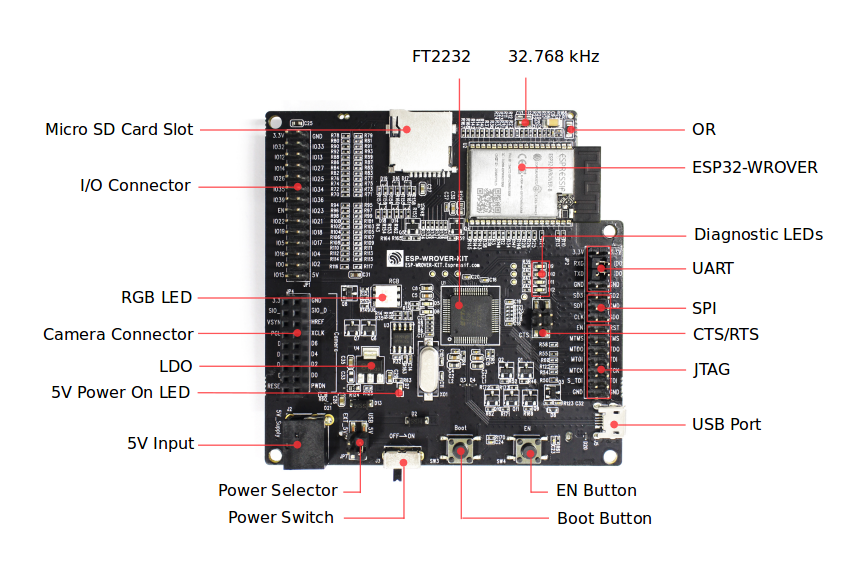
ESP-WROVER-KIT board layout - front¶ |
ESP-WROVER-KIT board layout - back¶ |
Features
ESP32-WROVER-B module
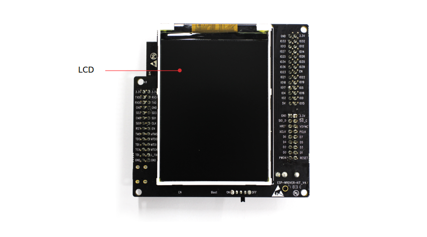
LCD screen
MicroSD card slot
Its another distinguishing feature is the embedded FTDI FT2232HL chip, an advanced multi-interface USB bridge. This chip enables to use JTAG for direct debugging of ESP32 through the USB interface without a separate JTAG debugger. ESP-WROVER-KIT makes development convenient, easy, and cost-effective.
Most of the ESP32 I/O pins are broken out to the board’s pin headers for easy access.
Serial Console
UART0 is, by default, the serial console. It connects to the on-board FT2232HL converter and is available on the USB connector USB CON8 (J5).
It will show up as /dev/ttyUSB[n] where [n] will probably be 1, since the first interface ([n] == 0) is dedicated to the USB-to-JTAG interface.
Buttons and LEDs
Buttons
There are two buttons labeled Boot and EN. The EN button is not available to software. It pulls the chip enable line that doubles as a reset line.
The BOOT button is connected to IO0. On reset it is used as a strapping pin to determine whether the chip boots normally or into the serial bootloader. After reset, however, the BOOT button can be used for software input.
LEDs
There are several on-board LEDs for that indicate the presence of power and USB activity.
There is an RGB LED available for software.
Pin Mapping
Pin |
Signal |
Notes |
|---|---|---|
0 |
RGB LED Red / BOOT Button |
|
2 |
RGB LED Green |
|
4 |
RGB LED Blue |
|
5 |
LCD Backlight |
|
18 |
LCD Reset |
|
19 |
LCD Clock |
|
21 |
LCD D/C |
|
22 |
LCD CS |
|
23 |
LCD MOSI |
|
25 |
LCD MISO |
Configurations
nsh
Basic NuttShell configuration (console enabled in UART0, exposed via USB connection by means of FT2232HL converter, at 115200 bps).
wapi
Enables Wi-Fi support.
gpio
This is a test for the GPIO driver. It includes the 3 LEDs and one, arbitrary, GPIO. For this example, GPIO22 was used. At the nsh, we can turn LEDs on and off with the following:
nsh> gpio -o 1 /dev/gpio0
nsh> gpio -o 0 /dev/gpio0
We can use the interrupt pin to send a signal when the interrupt fires:
nsh> gpio -w 14 /dev/gpio2
The pin is configured to as a rising edge interrupt, so after issuing the above command, connect it to 3.3V.
spiflash
This config tests the external SPI that comes with an ESP32 module connected through SPI1.
By default a SmartFS file system is selected. Once booted you can use the following commands to mount the file system:
mksmartfs /dev/smart0
mount -t smartfs /dev/smart0 /mnt
Note that mksmartfs is only needed the first time.
nx
This config adds a set of tests using the graphic examples at apps/example/nx.
This configuration illustrates the use of the LCD with the lower performance SPI interface.
lvgl
This is a demonstration of the LVGL graphics library running on the NuttX LCD driver. You can find LVGL here:
https://www.lvgl.io/
https://github.com/lvgl/lvgl
This configuration uses the LVGL demonstration at apps/examples/lvgldemo.