ESP32 DevKitC
The ESP32 DevKitC is a development board for the ESP32 SoC from Espressif, based on a ESP-WROOM-32 module. You can find the original V2 version and the newer V4 variant. They are pin compatible.
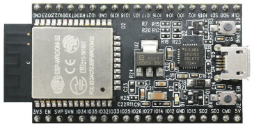
ESP32 DevKitC/Core V2¶ |
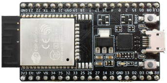
ESP32 DevKitC V4¶ |
Features
ESP32 WROOM Module
USB-to-UART bridge via micro USB port
Power LED
EN and BOOT buttons (BOOT accessible to user)
SPI FLASH (size varies according to model
Serial Console
UART0 is, by default, the serial console. It connects to the on-board CP2102 converter and is available on the USB connector USB CON8 (J1).
It will show up as /dev/ttypUSB[n] where [n] will probably be 0 (is it 1 on my PC because I have a another device at ttyUSB0).
Buttons and LEDs
Buttons
There are two buttons labeled Boot and EN. The EN button is not available to software. It pulls the chip enable line that doubles as a reset line.
The BOOT button is connected to IO0. On reset it is used as a strapping pin to determine whether the chip boots normally or into the serial bootloader. After reset, however, the BOOT button can be used for software input.
LEDs
There are several on-board LEDs for that indicate the presence of power and USB activity. None of these are available for use by software.
Ethernet
ESP32 has a 802.11 hardware MAC, so just connects to external PHY chip. Due to the limited number of GPIOs in ESP32, it’s recommended to use RMII to connect to an external PHY chip. Current driver also only supports RMII option.
The RMII GPIO pins are fixed, but the SMI and functional GPIO pins are optional.
RMII GPIO pins are as following:
ESP32 GPIO          PHY Chip GPIO
  IO25       <-->       RXD[0]
  IO26       <-->       RXD[1]
  IO27       <-->       CRS_DV
  IO0        <-->       REF_CLK
  IO19       <-->       TXD[0]
  IO21       <-->       TX_EN
  IO22       <-->       TXD[1]
SMI GPIO pins (default option) are as following:
ESP32 GPIO          PHY Chip GPIO
  IO18       <-->       MDIO
  IO23       <-->       MDC
Functional GPIO pins(default option) are as following:
ESP32 GPIO          PHY Chip GPIO
  IO5        <-->      Reset_N
Espressif has an official Ethernet development board.
This driver has been tested according to this board and ESP32 core board + LAN8720 module. If users have some issue about using this driver, please refer the upper official document, specially the issue that GPIO0 causes failing to bring the ESP32 chip up.
Configurations
nsh
Basic NuttShell configuration (console enabled in UART0, exposed via USB connection by means of CP2102 converter, at 115200 bps).
wapi
Enables Wi-Fi support. You can define your credentials this way:
$ make menuconfig
-> Application Configuration
    -> Network Utilities
        -> Network initialization (NETUTILS_NETINIT [=y])
            -> WAPI Configuration
Or if you don’t want to keep it saved in the firmware you can do it at runtime:
nsh> wapi psk wlan0 mypasswd 1
nsh> wapi essid wlan0 myssid 1
nsh> renew wlan0
wifinsh
The wifinsh is similar to the wapi board example, but it will connect
automatically to your Access Point (Wi-Fi Router) and will run telnet daemon
in the board. Then you can connect to your board from your computer using the
telnet program.
After configuring the esp32-devkit:wifinsh you need to define your creden-
tials in the menuconfig. You can define your credentials this way:
$ make menuconfig
-> Application Configuration
    -> Network Utilities
        -> Network initialization (NETUTILS_NETINIT [=y])
            -> WAPI Configuration
Find your board IP using nsh> ifconfig and then from your computer:
$ telnet 192.168.x.y
Where x and y are the last two numbers of the IP that your router gave to your board.
mqttc
This configuration tests the MQTT-C publisher example.
From the host, start the broker and subscribe to the test topic. Using
mosquitto this should be:
$ mosquitto&
$ mosquitto_sub -t test
From the NSH, connect to an access point:
nsh> wapi psk wlan0 mypasswd 1
nsh> wapi essid wlan0 myssid 1
nsh> renew wlan0
Publish to the broker:
nsh> mqttc_pub -h 192.168.1.11
The default behavior is to publish the message test. The following should be
outputted:
nsh> mqttc_pub -h 192.168.1.11
     Success: Connected to broker!
     Success: Published to broker!

     Disconnecting from 192.168.1.11
From the host the message test should be outputted.
smp
Another NSH configuration, similar to nsh, but also enables SMP operation. It differs from the nsh configuration only in these additional settings:
SMP is enabled:
CONFIG_SMP=y
CONFIG_SMP_NCPUS=2
CONFIG_SPINLOCK=y
The apps/testing/smp test is included:
CONFIG_TESTING_SMP=y
CONFIG_TESTING_SMP_NBARRIER_THREADS=8
CONFIG_TESTING_SMP_PRIORITY=100
CONFIG_TESTING_SMP_STACKSIZE=2048
ostest
This is the NuttX test at apps/testing/ostest that is run against all new architecture ports to assure a correct implementation of the OS. The default version is for a single CPU but can be modified for an SMP test by adding:
CONFIG_SMP=y
CONFIG_SMP_NCPUS=2
CONFIG_SPINLOCK=y
mcp2515
This config is used to communicate with MCP2515 CAN over SPI chip. SPI3 is used and kept with the default IOMUX pins, i.e.:
CS   --> 5
SCK  --> 18
MOSI --> 23
MISO --> 19
The MCP2515 interrupt (INT) pin is connected to the pin 22 of the ESP32-Devkit.
mmcsdspi
This config tests the SPI driver by connecting an SD Card reader over SPI. SPI2 is used and kept with the default IOMUX pins, i.e.:
CS   --> 15
SCK  --> 14
MOSI --> 13
MISO --> 12
Once booted the following command is used to mount a FAT file system:
nsh> mount -t vfat /dev/mmcsd0 /mnt
module
This config is to run apps/examples/module.
sotest
This config is to run apps/examples/sotest.
spiflash
This config tests the external SPI that comes with an ESP32 module connected through SPI1.
By default a SmartFS file system is selected. Once booted you can use the following commands to mount the file system:
nsh> mksmartfs /dev/smart0
nsh> mount -t smartfs /dev/smart0 /mnt
Note that mksmartfs is only needed the first time.
psram
This config tests the PSRAM driver over SPIRAM interface. You can use the ramtest command to test the PSRAM memory. We are testing only 64KB on this example (64 * 1024), but you can change this number to 2MB or 4MB depending on PSRAM chip used on your board:
nsh> ramtest -w 0x3F800000 65536
RAMTest: Marching ones: 3f800000 65536
RAMTest: Marching zeroes: 3f800000 65536
RAMTest: Pattern test: 3f800000 65536 55555555 aaaaaaaa
RAMTest: Pattern test: 3f800000 65536 66666666 99999999
RAMTest: Pattern test: 3f800000 65536 33333333 cccccccc
RAMTest: Address-in-address test: 3f800000 65536
timer
This config test the general use purpose timers. It includes the 4 timers, adds driver support, registers the timers as devices and includes the timer example.
To test it, just run the following:
nsh> timer -d /dev/timerx
Where x in the timer instance.
watchdog
This config test the watchdog timers. It includes the 2 MWDTS, adds driver support, registers the WDTs as devices and includes the watchdog example.
To test it, just run the following:
nsh> wdog -d /dev/watchdogx
Where x in the watchdog instance.