ESP32-S2-Kaluga-1 Kit v1.3
The ESP32-S2-Kaluga-1 kit v1.3 is a development kit by Espressif that is mainly created to:
Demonstrate the ESP32-S2’s human-computer interaction functionalities
Provide the users with the tools for development of human-computer interaction applications based on the ESP32-S2
There are many ways of how the ESP32-S2’s abundant functionalities can be used. For starters, the possible use cases may include:
Smart home: From simplest smart lighting, smart door locks, smart sockets, to video streaming devices, security cameras, OTT devices, and home appliances
Battery-powered equipment: Wi-Fi mesh sensor networks, Wi-Fi-networked toys, wearable devices, health management equipment
Industrial automation equipment: Wireless control and robot technology, intelligent lighting, HVAC control equipment, etc.
Retail and catering industry: POS machines and service robots
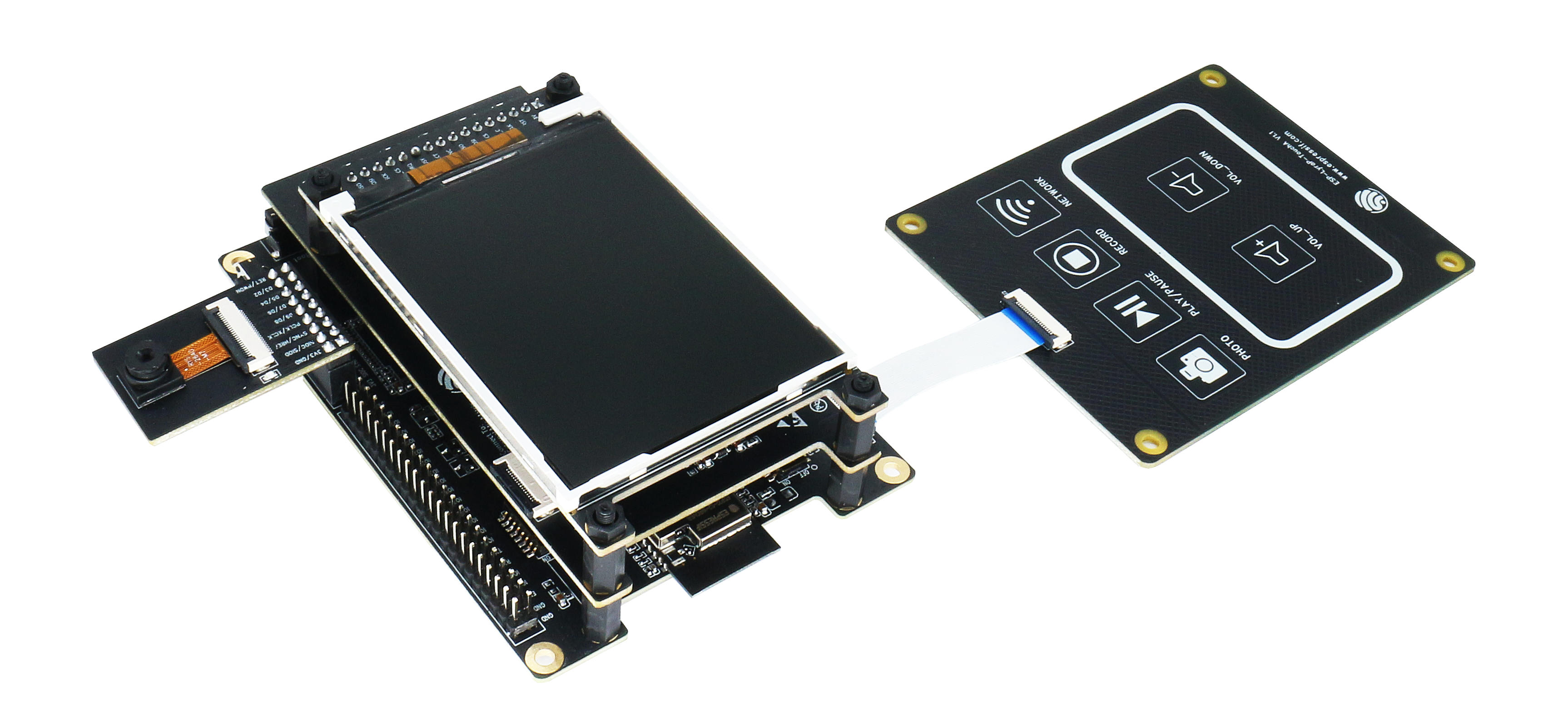
ESP32-S2-Kaluga-1-Kit Overview (click to enlarge)
The ESP32-S2-Kaluga-1 kit consists of the following boards:
Main board: ESP32-S2-Kaluga-1
Extension boards:
ESP-LyraT-8311A - Audio player
ESP-LyraP-TouchA - Touch buttons
ESP-LyraP-LCD32 - 3.2” LCD screen
ESP-LyraP-CAM - Camera module
A block diagram below shows the components of the ESP32-S2-Kaluga-1 and their interconnections.
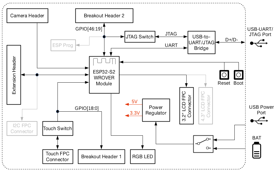
ESP32-S2-Kaluga-1 block diagram
Features
The ESP32-S2-Kaluga-1 main board is the heart of the kit. It integrates the ESP32-S2-WROVER module and all the connectors for extension boards. This board is the key tool in prototyping human-computer interaction interfaces.
The ESP32-S2-Kaluga-1 board has connectors for boards with:
Extension header (ESP-LyraT-8311A, ESP-LyraP-LCD32)
Camera header (ESP-LyraP-CAM)
Touch FPC coneector (ESP-LyraP-TouchA)
LCD FPC connector (no official extension boards yet)
I2C FPC connector (no official extension boards yet)
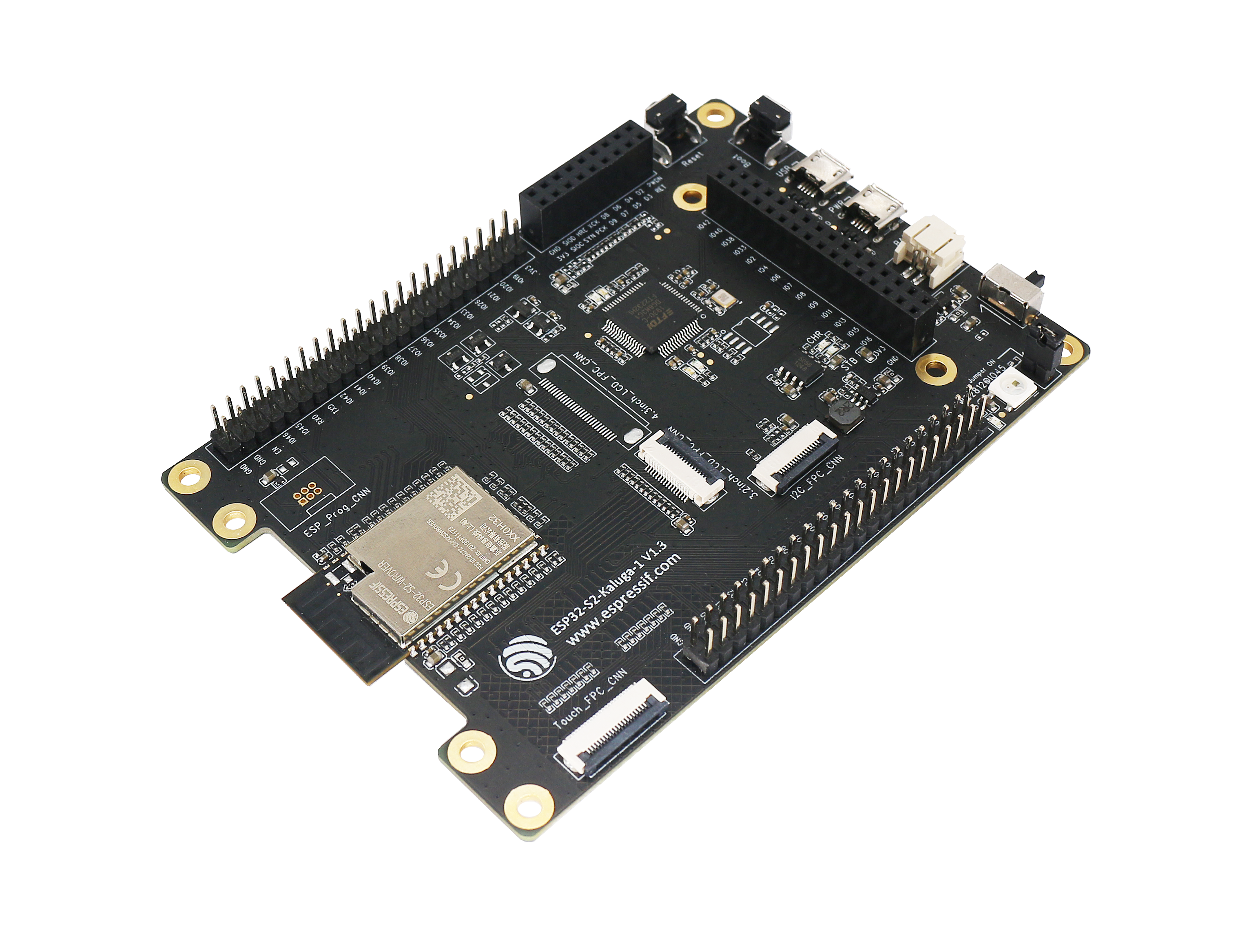
ESP32-S2-Kaluga-1 (click to enlarge)
All the four extension boards are specially desgined to support the following features:
- Touch panel control
Six touch buttons
Supports acrylic panels up to 5 mm
Wet hand operation
Water rejection, ESP32-S2 can be configured to disable all touchpads automatically if multiple pads are simultaneously covered with water and to re-enable touchpads if the water is removed
- Audio playback
Connect speakers to play audio
Use together with the Touch panel to control audio playback and adjust volume
- LCD display
LCD interface (8-bit parallel RGB, 8080, and 6800 interface)
- Camera image acquisition
Supports OV2640 and OV3660 camera modules
8-bit DVP image sensor interface (ESP32-S2 also supports 16-bit DVP image sensors, you can design it yourself)
Clock frequency up to 40 MHz
Optimized DMA transmission bandwidth for easier transmission of high-resolution images
Compatibility of Extension Boards
If you want to use more than one extension board at the same time, please check the table given below.
Boards Used |
HW Conflict |
Limitations |
Solution |
|---|---|---|---|
8311A v1.3 + CAM v1.1 |
I2S Controller |
ESP32-S2 has only one I2S interface. But both extension boards require connection via the ESP32-S2’s I2S interface (LyraT-8311A in Standard mode, ESP-LyraP-CAM in Camera mode). |
Utilize time division multiple access, or use a different audio module that can be connected via other GPIOs or DAC. |
TouchA v1.1 + LCD32 v1.2 |
IO11, IO6 |
Touch actions cannot be triggered because of the multiplexed pin IO11. ESP-LyraP-LCD32 will not be affected because its BLCT pin will be disconnected from IO6. |
Do not initialize IO11 (NETWORK) for your ESP-LyraP-TouchA, or configure the BLCT pin to -1 (= do not use BLCT) for your ESP-LyraP-LCD32. |
8311A v1.3 + LCD32 v1.2 |
IO6 |
BLCT pin of ESP32-S2-Kaluga-1 will be disconnected from IO6. |
Configure the BK pin to -1 (= do not use BLCT) for your ESP-LyraP-LCD32. |
TouchA v1.1 + 8311A v1.3 |
Pin BT_ADC on ESP-LyraT-8311A |
This pin is required for initialization of the six button on ESP-LyraT-8311A. At the same time, ESP-LyraP-TouchA needs this pin for its touch actions. |
If you plan to use buttons on ESP-LyraT-8311A, do not initialize pin IO6 (PHOTO) for your ESP-LyraP-TouchA. |
TouchA v1.1 + CAM v1.1 |
IO1, IO2, IO3 |
Cannot be used simultaneously because of the mentioned multiplexed pins. |
For ESP-LyraP-TouchA, do not initialize IO1 (VOL_UP), IO2 (PLAY), and IO3 (VOL_DOWN). |
TouchA v1.1 + LCD32 v1.2 + CAM v1.1 |
IO1, IO2, IO3, IO11 |
Conflicts on the mentioned multiplexed pins. |
For ESP-LyraP-TouchA, do not initialize IO1 (VOL_UP), IO2 (PLAY), IO3 (VOL_DOWN), and IO11 (NETWORK). |
TouchA v1.1 + LCD32 v1.2 + 8311A v1.3 |
IO6, IO11 |
If ESP-LyraT-8311A’s pin BT_ADC is used to initialize the board’s six buttons, IO6 and IO11 will not be available for the other boards. |
Do not initialize IO11 (NETWORK) for your ESP-LyraP-TouchA. Also, if you need to use BT_ADC, do not initialize IO6 (PHOTO). |
Also, all extension boards and the JTAG interface share the same pins IO39, IO40, IO41 and IO42. For this reason, the following may disturb the JTAG operation:
Plugging in any extension board
Debugging an application that is using an extension board
Serial Console
UART0 is, by default, the serial console. It connects to the on-board CP2102 converter and is available on the micro-USB connector (J1).
It will show up as /dev/ttyUSB[n] where [n] will probably be 0.
Configurations
All of the configurations presented below can be tested by running the following commands:
$ ./tools/configure.sh esp32s2-kaluga-1:<config_name>
$ make flash ESPTOOL_PORT=/dev/ttyUSB0 -j
Where <config_name> is the name of board configuration you want to use, i.e.: nsh, buttons, wifi…
Then use a serial console terminal like picocom configured to 115200 8N1.
nsh
Basic NuttShell configuration (console enabled in UART0, exposed via USB connection by means of CP2102 converter, at 115200 bps).