ESP32-C3 DevKit
The ESP32-C3 DevKit is an entry-level development board equipped with either an ESP32-C3-WROOM-02 or an ESP32-C3-MINI-1. ESP32-C3-WROOM-02 and ESP32-C3-MINI-1 are SoMs based on the RISC-V ESP32-C3 CPU.
Most of the I/O pins are broken out to the pin headers on both sides for easy interfacing. Developers can either connect peripherals with jumper wires or mount ESP32-C3 DevKit on a breadboard.
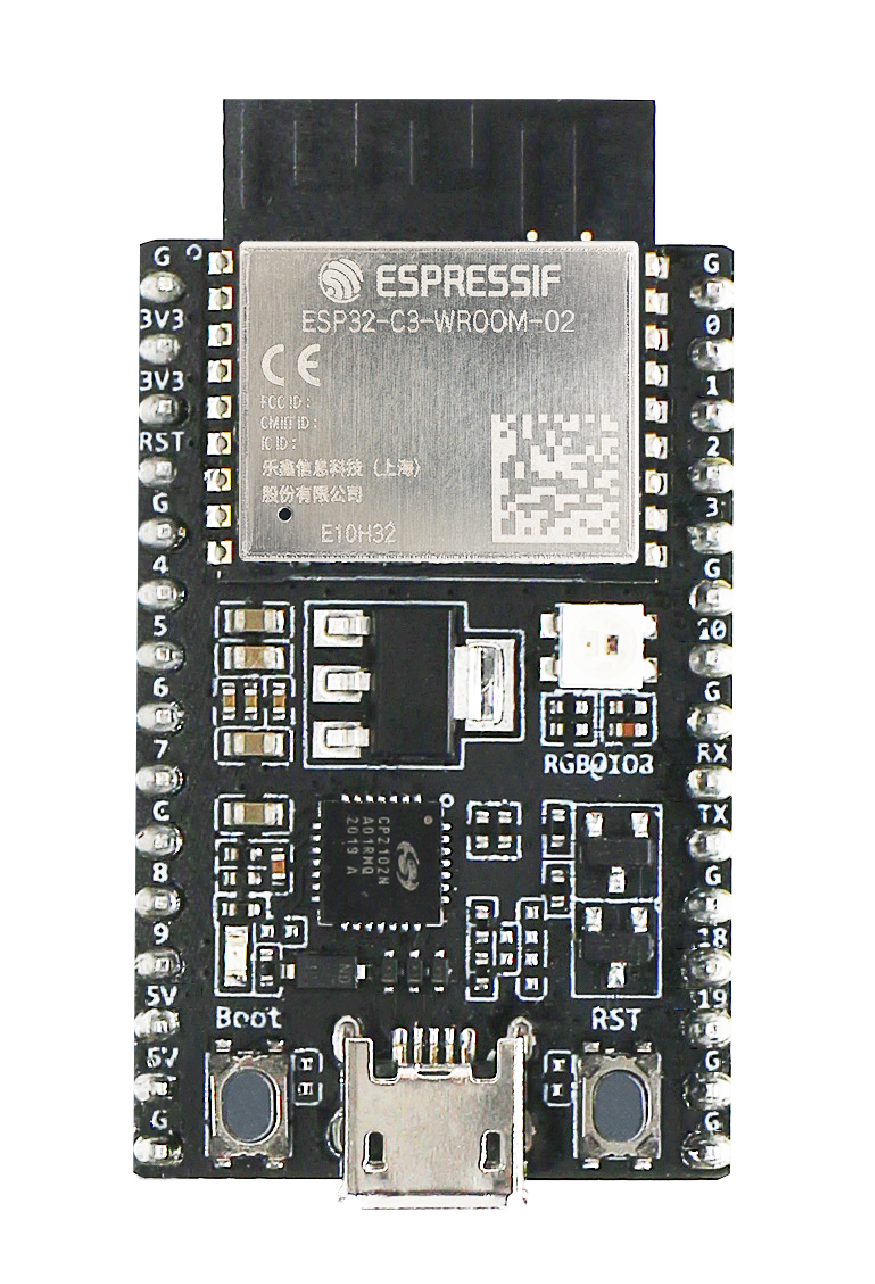
ESP32-C3-DevKitC-02 |
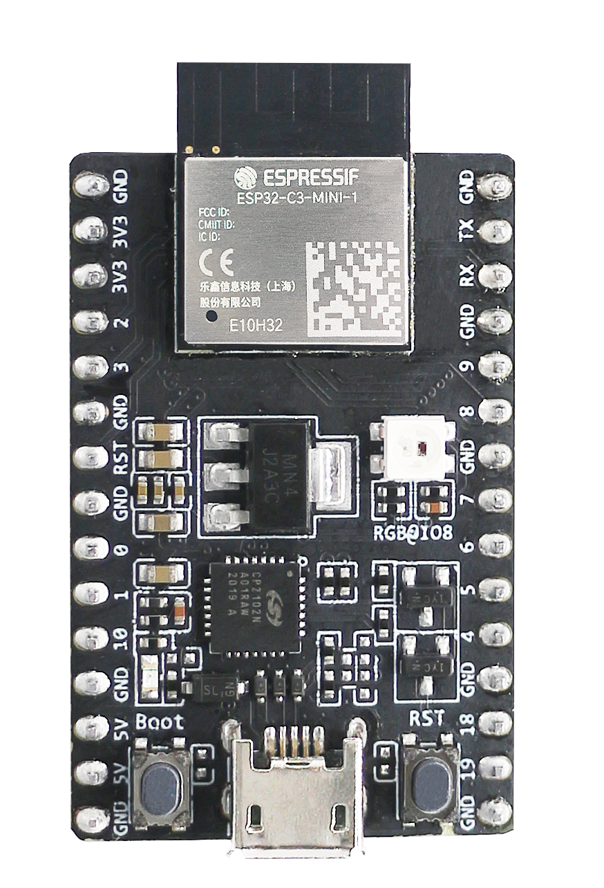
ESP32-C3-DevKitM-1 |
Configurations
All of the configurations presented below can be tested by running the following commands:
$ ./tools/configure.sh esp32c3-devkit:<config_name>
$ make flash ESPTOOL_PORT=/dev/ttyUSB0 -j
Where <config_name> is the name of board configuration you want to use, i.e.: nsh, buttons, wifi…
Then use a serial console terminal like picocom configured to 115200 8N1.
adc
This configuration demonstrates the use of the internal Analog to Digital Converter (ADC).
To check it, you can execute the adc application:
nsh> adc
adc_main: g_adcstate.count: 0
adc_main: Hardware initialized. Opening the ADC device: /dev/adc0
Sample:
1: channel: 0 value: 870
Sample:
1: channel: 0 value: 870
Sample:
1: channel: 0 value: 865
Sample:
1: channel: 0 value: 859
autopm
This configuration makes the device automatically enter the low power consumption mode when in the idle state, powering off the cpu and other peripherals.
In minimum power save mode, the station wakes up every DTIM to receive a beacon. The broadcast data will not be lost because it is transmitted after DTIM. However, it can not save much more power if DTIM is short as the DTIM is determined by the access point.
ble
This configuration is used to enable the Bluetooth Low Energy (BLE) of ESP32-C3 chip.
To test it, just run the following commands below.
Confirm that bnep interface exist:
nsh> ifconfig
bnep0   Link encap:UNSPEC at DOWN
    inet addr:0.0.0.0 DRaddr:0.0.0.0 Mask:0.0.0.0
Get basic information from it:
nsh> bt bnep0 info
Device: bnep0
BDAddr: 86:f7:03:09:41:4d
Flags:  0000
Free:   20
  ACL:  20
  SCO:  0
Max:
  ACL:  24
  SCO:  0
MTU:
  ACL:  70
  SCO:  70
Policy: 0
Type:   0
Start the scanning process:
nsh> bt bnep0 scan start
Wait a little bit before stopping it.
Then after some minutes stop it:
nsh> bt bnep0 scan stop
Get the list of BLE devices found around you:
nsh> bt bnep0 scan get
Scan result:
1.     addr:           d7:c4:e6:xx:xx:xx type: 0
       rssi:            -62
       response type:   4
       advertiser data: 10 09 4d 69 20 XX XX XX XX XX XX XX XX XX XX 20                      e
2.     addr:           cb:23:18:xx:xx:xx type: 0
       rssi:            -60
       response type:   0
       advertiser data: 02 01 06 1b ff XX XX XX ff ff ff ff ff ff ff ff                      8
3.     addr:           cb:23:18:xx:xx:xx type: 0
       rssi:            -60
       response type:   4
       advertiser data: 10 09 4d 69 20 XX XX XX XX XX XX XX XX XX XX 20                      e
4.     addr:           d7:c4:e6:xx:xx:xx type: 0
       rssi:            -62
       response type:   0
       advertiser data: 02 01 06 1b ff XX XX XX ff ff ff ff ff ff ff ff                      e
5.     addr:           d7:c4:e6:xx:xx:xx type: 0
       rssi:            -62
       response type:   4
       advertiser data: 10 09 4d 69 20 XX XX XX XX XX XX XX XX XX XX 20                      e
nsh>
bmp180
This configuration enables the use of the BMP180 pressure sensor over I2C.
You can check that the sensor is working by using the bmp180 application:
nsh> bmp180
Pressure value = 91531
Pressure value = 91526
Pressure value = 91525
coremark
This configuration sets the CoreMark benchmark up for running on the maximum number of cores for this system. It also enables some optimization flags and disables the NuttShell to get the best possible score.
Note
As the NSH is disabled, the application will start as soon as the system is turned on.
crypto
This configuration enables support for the cryptographic hardware and
the /dev/crypto device file.
cxx
Development enviroment ready for C++ applications. You can check if the setup
was successfull by running cxxtest:
nsh> cxxtest
Test ofstream ================================
printf: Starting test_ostream
printf: Successfully opened /dev/console
cout: Successfully opened /dev/console
Writing this to /dev/console
Test iostream ================================
Hello, this is only a test
Print an int: 190
Print a char: d
Test std::vector =============================
v1=1 2 3
Hello World Good Luck
Test std::map ================================
Test C++17 features ==========================
File /proc/meminfo exists!
Invalid file! /invalid
File /proc/version exists!
efuse
This configuration demonstrates the use of the eFuse driver. It can be accessed
through the /dev/efuse device file.
elf
This configuration uses apps/examples/elf in order to test the ELF loader.
It can be tested by executing the elf application.
gpio
This is a test for the GPIO driver. It uses GPIO1 and GPIO2 as outputs and GPIO9 as an interrupt pin.
At the nsh, we can turn the outputs on and off with the following:
nsh> gpio -o 1 /dev/gpio0
nsh> gpio -o 1 /dev/gpio1

nsh> gpio -o 0 /dev/gpio0
nsh> gpio -o 0 /dev/gpio1
We can use the interrupt pin to send a signal when the interrupt fires:
nsh> gpio -w 14 /dev/gpio2
The pin is configured as a rising edge interrupt, so after issuing the above command, connect it to 3.3V.
knsh
This is identical to the nsh configuration except that (1) NuttX is built as PROTECTED mode, monolithic module and the user applications are built separately and, as a consequence, (2) some features that are only available in the FLAT build are disabled.
Protected Mode support for ESP32-C3 relies on the RISC-V Physical Memory Protection (PMP) for implementing isolation between Kernel and Userspace. The Kernel configures the PMP to restrict the application access to selected peripherals and specific regions of on-chip memories (Internal ROM and Internal SRAM) and of the External Flash.
lvgl
This is a demonstration of the LVGL graphics library running on the NuttX LCD driver. You can find LVGL here:
https://www.lvgl.io/
https://github.com/lvgl/lvgl
This configuration uses the LVGL demonstration at apps/examples/lvgldemo.
mcuboot_slot_confirm
This configuration is used to represent an MCUboot update image that needs to be confirmed after flashing. The image can be confirmed by using the following command:
nsh> mcuboot_confirm
Application Image successfully confirmed!
For more information, check this demo.
module
This config is to run apps/examples/module.
nsh
Basic configuration to run the NuttShell (nsh).
nvcfgdata
This configuration enables the MTD failsafe mode. You can test it
by running the mtdconfig_fs_test application:
nsh> mtdconfig_fs_test
test_nvs_mount: test begin
test_nvs_mount: success
test_nvs_write: test begin
test_nvs_write: success
test_nvs_corrupt_expire: test begin
test_nvs_corrupt_expire: success
test_nvs_corrupted_write: test begin
test_nvs_corrupted_write: success
test_nvs_gc: test begin
test_nvs_gc: success
test_nvs_gc_3sectors: test begin
test_nvs_gc_3sectors: success
test_nvs_corrupted_sector_close: test begin
test_nvs_corrupted_sector_close: success
test_nvs_full_sector: test begin
test_nvs_full_sector: success
test_nvs_gc_corrupt_close_ate: test begin
test_nvs_gc_corrupt_close_ate: success
test_nvs_gc_corrupt_ate: test begin
test_nvs_gc_corrupt_ate: success
test_nvs_gc_touched_deleted_ate: test begin
test_nvs_gc_touched_deleted_ate: success
test_nvs_gc_touched_expired_ate: test begin
test_nvs_gc_touched_expired_ate: success
test_nvs_gc_not_touched_expired_ate: test begin
test_nvs_gc_not_touched_expired_ate: success

Final memory usage:
VARIABLE  BEFORE   AFTER    DELTA
======== ======== ======== ========
arena       5bf30    5bf30        0
ordblks         1        1        0
mxordblk    59100    59100        0
uordblks     2e30     2e30        0
fordblks    59100    59100        0
oneshot
This config demonstrate the use of oneshot timers present on the ESP32.
To test it, just run the oneshot example:
nsh> oneshot
Opening /dev/oneshot
Maximum delay is 4294967295999999
Starting oneshot timer with delay 2000000 microseconds
Waiting...
Finished
ostest
This is the NuttX test at apps/testing/ostest that is run against all new
architecture ports to assure a correct implementation of the OS.
pm
This configuration enables the CPU power management through governors.
pwm
This configuration demonstrates the use of PWM through a LED connected to GPIO2.
To test it, just execute the pwm application:
nsh> pwm
pwm_main: starting output with frequency: 10000 duty: 00008000
pwm_main: stopping output
random
This configuration shows the use of the ESP32-C3’s True Random Number Generator with
entropy sourced from Wi-Fi and Bluetooth noise.
To test it, just run rand to get 32 randomly generated bytes:
nsh> rand
Reading 8 random numbers
Random values (0x3ffe0b00):
0000  98 b9 66 a2 a2 c0 a2 ae 09 70 93 d1 b5 91 86 c8  ..f......p......
0010  8f 0e 0b 04 29 64 21 72 01 92 7c a2 27 60 6f 90  ....)d!r..|.'`o.
romfs
This configuration enables the ROMFS file system. You can test it by
running the romfs example:
nsh> romfs
Mounting ROMFS filesystem at target=/usr/local/share with source=/dev/ram1
Traversing directory: /usr/local/share
  DIRECTORY: /usr/local/share/adir/
Traversing directory: /usr/local/share/adir
  FILE: /usr/local/share/adir/anotherfile.txt/
  DIRECTORY: /usr/local/share/adir/subdir/
Traversing directory: /usr/local/share/adir/subdir
  FILE: /usr/local/share/adir/subdir/subdirfile.txt/
Continuing directory: /usr/local/share/adir
  FILE: /usr/local/share/adir/yafile.txt/
Continuing directory: /usr/local/share
  FILE: /usr/local/share/afile.txt/
  FILE: /usr/local/share/hfile/
PASSED
rtc
This configuration demonstrates the use of the RTC driver through alarms. You can set an alarm, check its progress and receive a notification after it expires:
nsh> alarm 10
alarm_daemon started
alarm_daemon: Running
Opening /dev/rtc0
Alarm 0 set in 10 seconds
nsh> alarm -r
Opening /dev/rtc0
Alarm 0 is active with 10 seconds to expiration
nsh> alarm_daemon: alarm 0 received
sotest
This config is to run apps/examples/sotest.
spiflash
This config tests the external SPI that comes with the ESP32-C3 module connected through SPI1.
By default a SmartFS file system is selected. Once booted you can use the following commands to mount the file system:
nsh> mksmartfs /dev/smart0
nsh> mount -t smartfs /dev/smart0 /mnt
Note that mksmartfs is only needed the first time.
sta_softap
With this configuration you can run these commands to be able to connect your smartphone or laptop to your board:
nsh> ifup wlan1
nsh> dhcpd_start wlan1
nsh> wapi psk wlan1 mypasswd 3
nsh> wapi essid wlan1 nuttxap 1
In this case, you are creating the access point nuttxapp in your board and to
connect to it on your smartphone you will be required to type the password mypasswd
using WPA2.
The dhcpd_start is necessary to let your board to associate an IP to your smartphone.
tickless
This configuration enables the support for tickless scheduler mode.
timer
This config test the general use purpose timers. It includes the 4 timers, adds driver support, registers the timers as devices and includes the timer example.
To test it, just run the following:
nsh> timer -d /dev/timerx
Where x in the timer instance.
twai
This configuration enables the support for the TWAI (Two-Wire Automotive Interface) driver.
You can test it by running the can example:
nsh> can
nmsgs: 0
min ID: 1 max ID: 2047
Bit timing:
  Baud: 1000000
  TSEG1: 15
  TSEG2: 4
    SJW: 3
  ID:    1 DLC: 1
uid
Enables support for the BOARDIOC_UNIQUEID boardctl() command.
usbconsole
This configuration tests the built-in USB-to-serial converter found in ESP32-C3 (revision 3).
esptool can be used to check the version of the chip and if this feature is
supported. Running esptool.py -p <port> chip_id should have Chip is
ESP32-C3 (revision 3) in its output.
When connecting the board a new device should appear, a /dev/ttyACMX on Linux
or a /dev/cu.usbmodemXXX om macOS.
This can be used to flash and monitor the device with the usual commands:
make download ESPTOOL_PORT=/dev/ttyACM0
minicom -D /dev/ttyACM0
watchdog
This configuration tests the watchdog timers. It includes the 2 MWDTS, adds driver support, registers the WDTs as devices and includes the watchdog example application.
To test it, just run the following command:
nsh> wdog -i /dev/watchdogX
Where X is the watchdog instance.
watcher
This configuration tests the watchdog timers in the capture mode. It includes the 2 MWDTS, adds driver support, registers the WDTs as devices and includes the watcher and watched example applications.
To test it, just run the following command:
nsh> watcher
nsh> watched
wifi
Enables Wi-Fi support. You can define your credentials this way:
$ make menuconfig
-> Application Configuration
    -> Network Utilities
        -> Network initialization (NETUTILS_NETINIT [=y])
            -> WAPI Configuration
Or if you don’t want to keep it saved in the firmware you can do it at runtime:
nsh> wapi psk wlan0 mypasswd 3
nsh> wapi essid wlan0 myssid 1
nsh> renew wlan0