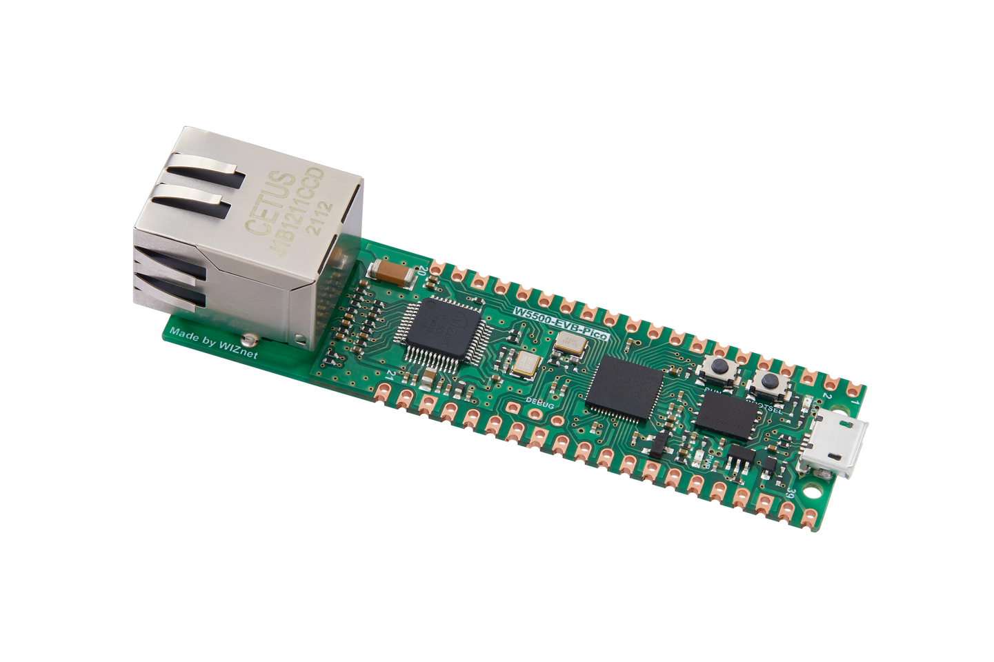
W5500-EVB-Pico
The W5500-EVB-Pico is a microcontroller evaluation board based on the Raspberry Pi RP2040 and fully hardwired TCP/IP controller W5500 – and basically works the same as Raspberry Pi Pico board but with additional Ethernet via W5500.
Features
RP2040 microcontroller chip
Dual-core ARM Cortex M0+ processor, flexible clock running up to 133 MHz
264kB of SRAM, and 2MB of on-board Flash memory
Castellated module allows soldering direct to carrier boards
USB 1.1 Host and Device support
Low-power sleep and dormant modes
Drag & drop programming using mass storage over USB
26 multi-function GPIO pins
2× SPI, 2× I2C, 2× UART, 3× 12-bit ADC, 16× controllable PWM channels
Accurate clock and timer on-chip
Temperature sensor
Accelerated floating point libraries on-chip
8 × Programmable IO (PIO) state machines for custom peripheral support
Ethernet port via WIZnet W5500, hardwired to SPI0 and two GPIO pins.
Pin Mapping
Pads numbered anticlockwise from USB connector.
Pad |
Signal |
Notes |
|---|---|---|
1 |
GPIO0 |
Default TX for UART0 serial console |
2 |
GPIO1 |
Default RX for UART1 serial console |
3 |
Ground |
|
4 |
GPIO2 |
|
5 |
GPIO3 |
|
6 |
GPIO4 |
|
7 |
GPIO5 |
|
8 |
Ground |
|
9 |
GPIO6 |
|
10 |
GPIO7 |
|
11 |
GPIO8 |
|
12 |
GPIO9 |
|
13 |
Ground |
|
14 |
GPIO10 |
|
15 |
GPIO11 |
|
16 |
GPIO12 |
|
17 |
GPIO13 |
|
18 |
Ground |
|
19 |
GPIO14 |
|
20 |
GPIO15 |
|
21 |
GPIO16 |
W5500 MISO |
22 |
GPIO17 |
W5500 CSn |
23 |
Ground |
|
24 |
GPIO18 |
W5500 SCLK |
25 |
GPIO19 |
W5500 MOSI |
26 |
GPIO20 |
W5500 RSTn |
27 |
GPIO21 |
W5500 INTn |
28 |
Ground |
|
29 |
GPIO22 |
|
30 |
Run |
|
31 |
GPIO26 |
ADC0 |
32 |
GPIO27 |
ADC1 |
33 |
AGND |
Analog Ground |
34 |
GPIO28 |
ADC2 |
35 |
ADC_VREF |
|
36 |
3V3 |
Power output to peripherals |
37 |
3V3_EN |
Pull to ground to turn off. |
38 |
Ground |
|
39 |
VSYS |
+5V Supply to board |
40 |
VBUS |
Connected to USB +5V |
Other RP2040 Pins
Signal |
Notes |
|---|---|
GPIO23 |
Output - Power supply control. |
GPIO24 |
Input - High if USB port or Pad 40 supplying power. |
GPIO25 |
Output - On board LED. |
ADC3 |
Input - Analog voltage equal to one third of VSys voltage. |
Separate pins for the Serial Debug Port (SDB) are available
Power Supply
The W5500-EVB-Pico can be powered via the USB connector, or by supplying +5V to pin 39. The board had a diode that prevents power from pin 39 from flowing back to the USB socket, although the socket can be power via pin 30.
The W5500-EVB-Pico chip run on 3.3 volts. This is supplied by an onboard voltage regulator. This regulator can be disabled by pulling pin 37 to ground.
The regulator can run in two modes. By default the regulator runs in PFM mode which provides the best efficiency, but may be switched to PWM mode for improved ripple by outputting a one on GPIO23.
Installation & Build
For instructions on how to to install the build dependencies and create a NuttX image for this board, consult the main RP2040 documentation.
Configurations
All configurations listed below can be configured using the following command in
the nuttx directory (again, consult the main RP2040 documentation):
$ ./tools/configure.sh w5500-evb-pico:<configname>
usbnsh
USB CDC/ACM serial console with NuttShell. TCP/IPv4 & IPv6 networking is supported via the Ethernet port.